


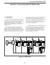

INTELLIGENT DISPATCH MODULE (IDM)
12-4
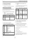
12.3 IDM ALIGNMENT SPECIFICATION
12.3.1 PRE-ALIGNMENT
The IDM is pre-aligned with the Basic Board
Module alignment procedures, refer to Section 7.3.
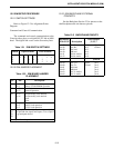
1. Main Rx Audio Level From J1:
a. Setup for alignment, input 1004 Hz tone at
-12 dBm into J1 EQU.
b. Set S5 for Test 1 (open section 1; close 2, 3 and 4).
c. Reset the module, press S2 and release.
d. Adjust R41 to -6 dBm ±0.5 dB at J11.
e. Verify that the level at TP5 is -6 dBm ±1 dB.
6. Main Tx Audio Output Level From J1:
a. Setup for alignment as in Step 1.
b. Adjust R83 for a -3 dBm ±0.5 dB level at TP3.
c. Adjust R44 for a -12 dBm ±0.5 dB level at J12.
4. Normal Operation:
a. Set S5 to 0, normal operation (Close sections 1, 2,
3 and 4).
b. Reset the module, Press S2 and release.
c. Remove the input alignment tone from J1.
NOTE: FSK is not aligned since it is not used on
the IDM.
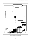
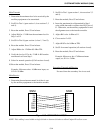
12.4 ALIGNMENT
Connections to the IDM may take several forms:
• Direct Connection
• Leased Lines
• Microwave Link
• T1 Channel Bank Interfaces
This ancillary equipment requires certain input
and output levels for proper operation. The module
should be adjusted accordingly.
Main Transmit
1. Determine the maximum level to be received by the
ancillary equipment to be transmitted.
2. Set S5 to Test 1 (open section 1, close sections 2, 3
and 4).
3. Reset the module, press S2 and release.
4. Adjust R44 for -12 dB from the maximum level in
step 1 at J12.
5. Set S5 for normal operation (all sections closed).
6. Reset the module, Press S2 and release.
Example: Microwave has -16 dBm maximum input,
set J12 for -28 dBm.
Main Receive
1. Determine the maximum transmit level that is sent
by the ancillary equipment to the interface module.
2. Set S5 to Test 1 (open section 1, close sections 2, 3
and 4)
3. Reset the module, press S2 and release.
4. Insert the maximum level determined in Step 1
using a 600 ohm audio oscillator into EQU port of
J1. Otherwise, set the ancillary equipment to send
the alignment tone to the interface module.
5. Adjust R41 to be -6 dBm at J11.
6. Set S5 for normal operation (all sections closed).
7. Reset the module, Press S2 and release.
Example: Microwave has +7 dBm maximum
output, set J11 for -5 dBm.