TELEPHONE INTERFACE MODULE (TIM)
14-4
14.1.8 TRANSMIT AUDIO
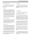
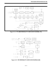
The transmit audio from the PCM channel stream
is processed to analog and sent to the telephone line
(see Figure 14-14). The functional paths of the
transmit audio are:
1. Voice Path
The transmit voice is processed from the PCM
channel stream by the same CODEC and time slot
determination circuitry as in the receive audio voice
path section above. The digitized voice is converted
to analog and filtered by the CODEC to a high pass
filter to eliminate low frequency audio. The audio
is level adjusted by an amplifier buffer and gated
into a summing amplifier buffer. The audio gating
provides on/off control of the voice audio to the
telephone line. The summing buffer has a level
adjustment to set the outgoing line level and drives
the unbalanced side of the telephone line hybrid.
2. Mobile Speech Detection
The audio for mobile speech detection comes from
the CODEC amplifier buffer. The bandpass filter is
centered at the audio frequency recognized for
voice peaks. The filtered audio is rectified and
detected for the presence of voice. The output of the
detector is an input to the logic unit.
3. DTMF Generation
The DTMF signaling is generated on the TIM and
transmitted toward the telephone line. The logic
unit provides the inputs to the DTMF generation
circuit. The generator outputs the desired tones and
is adjusted to the proper level with respect to the
voice path by an amplifier. The tones pass through
a logic unit controlled audio transmission gate,
summing amplifier buffer, to the telephone line.
14.2 4-WIRE E&M INTERFACE DESCRIPTION
The 4-Wire E&M Interface Card connects the
Switch with a 4-Wire audio circuit that supports Ear
and Mouth (E&M) signaling.
14.2.1 AUDIO
The audio circuit consists of a transmit (Tx) pair
and a receive (Rx) pair. The Tx pair transmits audio
and DTMF digits. The Rx pair receives audio and
DTMF digits. Dial Tone detection is also supported
by the Rx pair.
14.2.2 E&M LEADS
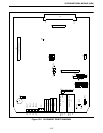
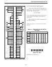
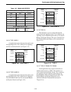
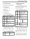
The E&M leads can be configured for Type I, II,
III, IV and V signaling by changing S201 on the
personality card (see Figure 14-21).
The E-Lead is a single input that monitors for -
48V, or ground. This lead is used to detect inbound
ringing (detected as battery reversals), receive pulse
dialed digits (detected as battery reversals), wink start
pulse (detected as a single battery reversal), and an
answer or hang-up by the connected circuit (detected
as a lead reversal). This lead can be set up for -48V or
ground idle states by changing S201, section 7 and 8.
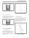
The M-Lead is a single output that signals to the
connected circuit with -48V, or ground. This lead is
used to request service (battery reversal), send a wink
start pulse (battery reversal), signal a hang-up or
answer to the circuit (battery reversal), transmit pulse
dial digits (sent as battery reversals). The state of this
lead is configured by S201, section 1 through 6.
NOTE: If this card is connected to a 2-Wire circuit, a
Termset is required. This card supports pulse dialing
for both inbound and outbound. Pulse dialing is
described as full battery reversal, not click detection
from the Central Office (CO). If click detection is
required, an external device is needed to support this
feature.
The E&M Interface Card installation instructions
are not for a specific installation because of the many
unique configurations. The field engineer customizes
or alters the installation for the appropriate interface
requirements.


