TELEPHONE INTERFACE MODULE (TIM)
14-28
Once the repeater channel is tuned, it is used as a
tool in tuning the interconnect channel. Average
audio transmitted to the CO is defined as -7 dBm.
±2 kHz of audio deviation in from a repeater is trans-
mitted to the CO at a level of -7 dBm. Similarly, -7
dBm going to the CO from a remote location results in
±2 kHz of audio transmitted from the Exciter. The
level at tip and ring locally, with -7 dBm injected
remotely, is the average audio level from the CO (-10
to -30 dBm, typically -20 dBm).
14.13 TUNING A DOD OR DID 2-WIRE INTER-
FACE TO THE 4-WIRE E&M BOARD.
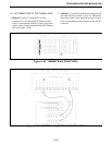
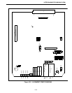
Refer to Figure 14-27 for this Section.
1. Establish an interconnect to a remote location, using
the DOD or DID line to be tuned.
2. Collect the call with a service monitor and encoder
box. Data level is 1 kHz.
3. Turn the radio off (do not end call). Monitor and
encoder are now collecting the call.
4. Inject a standard tone (±2 kHz audio) into the
receiver.
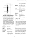
5. Use a bantam jack to monitor Tip and Ring (2-Wire
transmit in/monitor) at the Termset (see Figure 14-
28).
6. Adjust R44 (Tx Gain) on the E&M Main Board for
a level of -7 dBm (346 mV RMS, 978 mV P-P) at
Tip and Ring of the Termset. If R44 does not have
enough range, use dip switches on Tellabs cards for
more adjustment.
7. Adjust the balance circuit of the Termset (see
Figures 14-22 or 14-23) for minimum Exciter devi-
ation or RMS voltage at J11 on the E&M Main
Board. See Section 14.14 for additional information
on reflected energy levels from the CO.
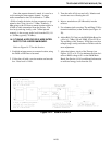
Figure 14-27 E&M INTERFACE


