SYSTEM RACK
4-13
4.3 SIX SHELF 3000 SERIES SWITCH
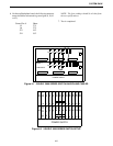
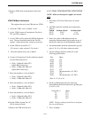
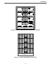
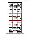
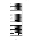
The system rack is a framework for modules that
consists of up to 6-shelves with 13-slots per shelf. In
each shelf, 12-slots are for function modules and
1-slot is reserved for the power module. The power
supplies for the shelves are located in the lower
portion of the rack framework. The framework also
provides support for interconnection wiring, routed
between shelves, and external devices.
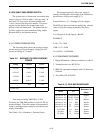
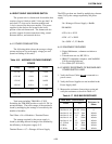
4.3.1 POWER CONSUMPTION
The following tables shows the average voltage,
current and power for each supply voltage per card
(based on loading of 72 cards).
Total watts including TIM-DID is 5.74W.
Excluding the TIM-DID provides a total of 4.3W for
normal modules. The total wattage of the terminal is
found by multiplying the wattage of a module by the
number of modules.
Total Watts x No. of Modules = Terminal Power
The wattage required by the power supply is
found by dividing the total wattage of the terminal by
the efficiency of the power supply (0.7).
Terminal Power ÷ 0.7 = Wattage of Power Supply
The BTUs per hour are found by multiplying a known
value (3.6) by the wattage required by the power
supply.
3.6 x Wattage of Power Supply = Btu/Hr.
EXAMPLE:
4.3W x 72 = 310W
310W ÷ 0.7 = 443W
3.6 x 443W = 1,595 Btu/Hr
4.3.2 EQUIPMENT REQUIRED
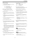
1. Digital Multimeter, voltmeter resolution to 0.001V.
2. Transmission test set, HP 3551A.
3. IBM NT compatible computer, with Call Processor
Software.
4. Two CIMs (023-3039-035)
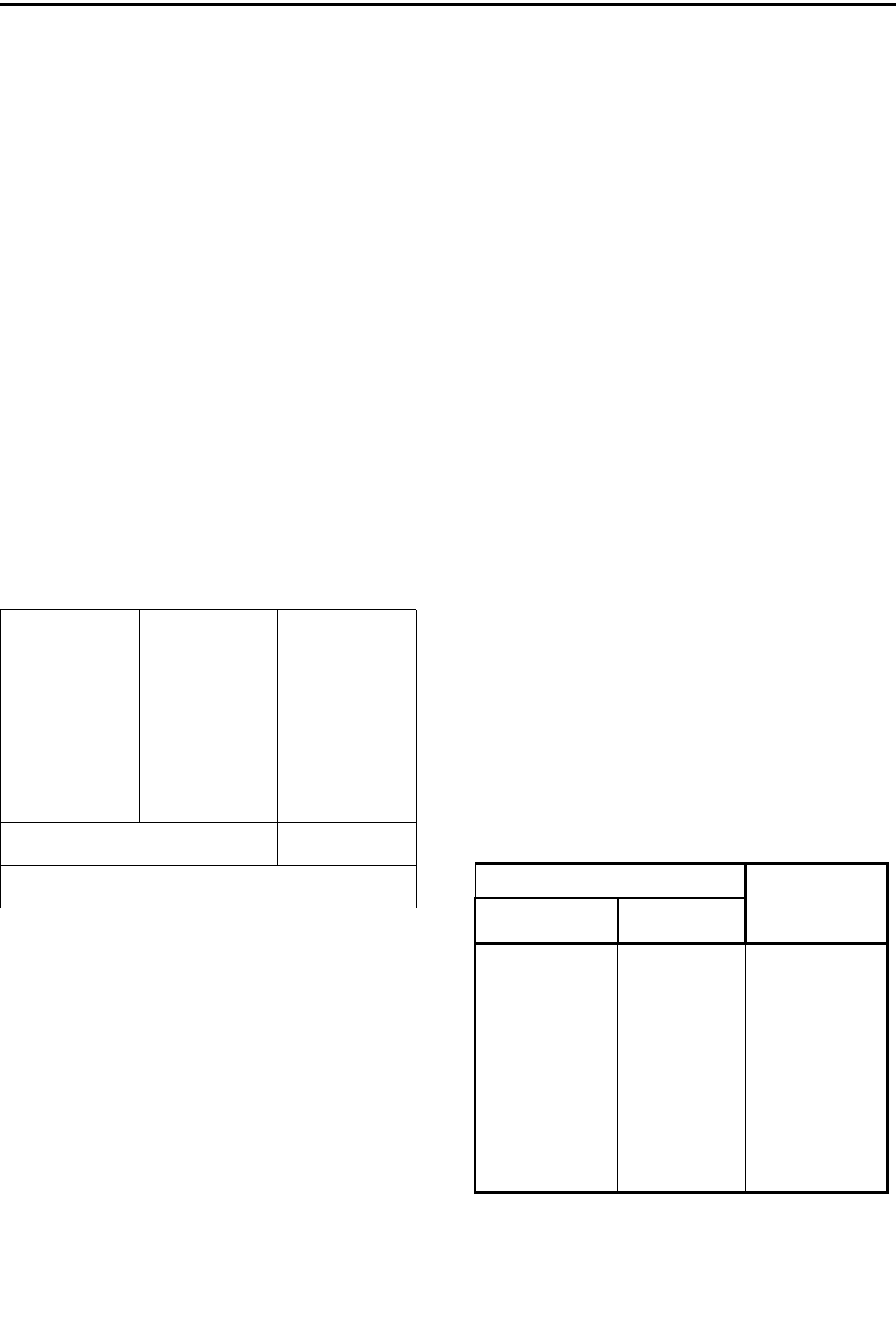
Table 4-11 AVERAGE VOLTAGE/CURRENT/
POWER
Voltage Current Power
+5V DC 0.50A 2.50W
+12V DC 0.10A 1.20W
-12V DC 0.05A 0.60W
-48V DC 0.03A* 1.44W
Total 5.74W
* DIDs only.
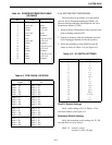
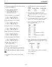
Table 4-12 BUS BAR RESISTANCE
Ohm Meter Lead Positions
Resistance in
Ohms
From To
Bus Bar A1-A2 Chassis/Frame Infinite
Bus Bar A1-A2 B1-B2 Black 0
Bus Bar A1-A2 C1-C2 Red Infinite
Bus Bar A1-A2 D1 Blue Infinite
Bus Bar A1-A2 E1 White Infinite
Bus Bar A1-A2 F1 Green Infinite
C1-C2 Red D1 Blue Infinite
D1-Blue E1 White Infinite
E1-White F1 Green Infinite


