


10-1
DISPATCH CHANNEL MODULE (DCM)
SECTION 10 DISPATCH CHANNEL MODULE (DCM)
10.1 DESCRIPTION
Refer to 3000 Series Switch Service Information
manual, Part No. 001-3139-102, for the component
layout, parts list and schematic. Refer to Figure 7-1 for
the Basic Board block diagram. The Dispatch Channel
Module (DCM) connects the Switch to a Conventional
Repeater. Each repeater has a DCM that controls the
repeater through logic signaling.
10.1.1 REPEATER SIGNALING
The DCM exchanges control information with the
CRM via Audio Frequency Shift Keying (AFSK) data
in a blank and burst mode on the voice audio path.
10.1.2 REPEATER CONTROL
The DCM monitors and controls the repeater
transmit, receives confirmation of all requests made to
the repeater and sends information the repeater
received.
10.1.3 VOICE CONNECTION
The DCM provides a 4-Wire 600 ohm balanced
voice connection to the repeater, converts audio to and
from Pulse Code Modulation (PCM), transmits and
receives on the PCM buses, and controls voice audio
gating to and from the repeater.
10.1.4 INTERNAL COMMUNICATION
The DCM uses the Intra-Terminal Data Bus
(IDB) to communicate to other modules and send
messages to and receive messages from the Call
Processor that controls its actions.
The DCM monitors the CSB to determine if a
CIM is active with the appropriate group.
10.2 DCM SETUP PROCEDURE
10.2.1 DCM SWITCH SETTINGS
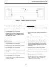
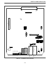
Refer to Figure 10-1 for the Alignment Points
Diagram.
Command and Control Communication
The command and control communication to the
Conventional Repeater Module (CRM) is by blank and
burst mode of Audio Frequency Shift Keyed data on
the Main audio lines.
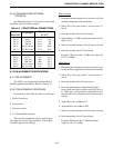
10.2.2 AFSK COMMUNICATION ON THE MAIN
LINES
Refer to Table 10-1 for switch settings.
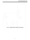
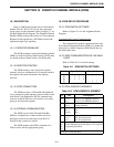
10.2.3 DCM JUMPER PLACEMENT
Table 10-1 DCM SWITCH SETTINGS
Switch Open Sections Close Sections
S1
S3
S4
S5
1
1
1
-
-
2
2
-
-
3
3
-
4
4
4
-
-
-
-
1
2
-
-
2
3
-
-
3
-
-
-
4
Table 10-2 DCM JUMPER PLACEMENT
JU Pin Description
J24 1 to 2*
2 to 3
Selects 27512 EPROM operation
Selects 27256 EPROM operation
J27 1 to 2
2 to 3*
Not used
Normal operation
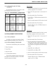
P33 1 to 2
3 to 4
5 and 6
open
open
open
J36 1 only
1 to 2
2 to 3
Not used
-48V E-lead operation
-15V E-lead operation
J14
J15
J21
J22
Jumper pin 1 to 2 for high impedance ground path
for split 600 ohm inputs and outputs. Leave open if
no ground path desired.
* Indicates normal operation.