


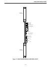

CHANNEL INTERFACE MODULE (CIM)
8-4
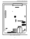
8.2.4 EXTERNAL CONNECTIONS
When connecting the CIM to a RIM or Multi-Net
Logic Drawer, cross connect the Tx lines with the Rx
lines. Connect the Secondary Tx and Rx lines with the
Drawers Tx and Rx Data lines.
8.3 CIM ALIGNMENT SPECIFICATIONS
8.3.1 PRE-ALIGNMENT
The CIM is pre-aligned with the Basic Board
Module alignment procedures, Refer to Section 7.3.
8.3.2 CIM ALIGNMENT PROCEDURE
Connections to the CIM may take several forms
as follows:
1. Direct Connection
2. Leased Lines
3. Microwave Link
4. T1 Channel Bank Interfaces
This ancillary equipment requires certain input and
output levels for proper operation. The module
should be adjusted accordingly.
Main Transmit
1. Determine the maximum level to be received by the
ancillary equipment to be transmitted.
2. Select Test 1 (S5, open section 1, close sections 2, 3
and 4).
3. Reset the module, Press S2 and release.
4. Adjust R44 for -12 dB from the maximum level in
Step 1 at J12.
5. Select for normal operation (S5 all sections closed).
6. Reset the module, Press S2 and release.
Example: Microwave has -16 dBm max input, Set
J12 for -28 dBm.
Main Receive
1. Determine the maximum transmit level that is sent
by the ancillary equipment to the interface module.
2. Select Test 1 (S5, open section 1, close sections 2, 3
and 4).
3. Reset the module, Press S2 and release.
4. Insert an alignment tone -12 dB from the level deter-
mined in Step 1 using a 600-ohm audio oscillator
into EQU port of J1. Otherwise, set the ancillary
equipment to send the alignment tone to the inter-
face module.
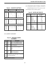
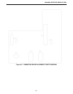
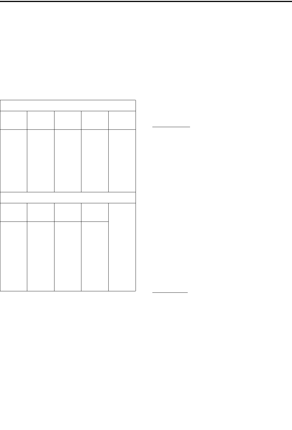
Table 8-4 CIM EXTERNAL CONNECTIONS
RIM to CIM CONNECTIONS
Label TB701 TB702
CIM/
P1
Label
RxDA+
RxDA-
TxDA+
TxDA-
RxA+
RxA-
TxA+
TxA-
pin 1
pin 2
pin 3
pin 4
pin 1
pin 2
pin 3
pin 4
-pin 59
-pin 60
-pin 27
-pin 28
-pin 63
-pin 64
-pin 31
-pin 32
TxS+
TxS-
RxS+
RxS-
RxA+
TxA-
RxA+
RxA-
MLM to CIM CONNECTIONS
Label TB 1
CIM/
P1
Label
GND
STA1
STA2
SRA1
SRA2
SRD1
SRD2
STD1
STD2
1
2
3
4
5
6
7
8
9
NC
-pin 31
-pin 32
-pin 63
-pin 64
-pin 59
-pin 60
-pin 27
-pin 28
RxA+
RxA-
TxA+
TxA-
TxS+
TxS-
RxS+
RxS-