


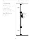
BASIC BOARD MODULE (BBM)
7-3
7.2 BBM SETUP PROCEDURE
Refer to the Tables in this section for switch
settings, jumper placements and the backplane wire
harness description. Also refer to Section 23 for more
information on the backplane.
7.2.1 SWITCH SETTINGS
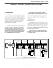
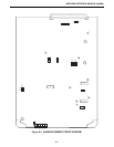
Refer to the Basic Board Module alignment
points diagram Figure 7-2 for the location of these
switches.
7.2.2 JUMPER PLACEMENT
Refer to the Basic Board Module alignment
points diagram Figure 7-2 for the location of these
jumpers.
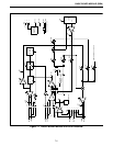
7.2.3 BBM BACKPLANE EXTERNAL
CONNECTIONS
See the Backplane Section 23 for pin-outs on the
shelf backplane and wire harness pin-outs.
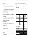
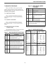
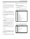
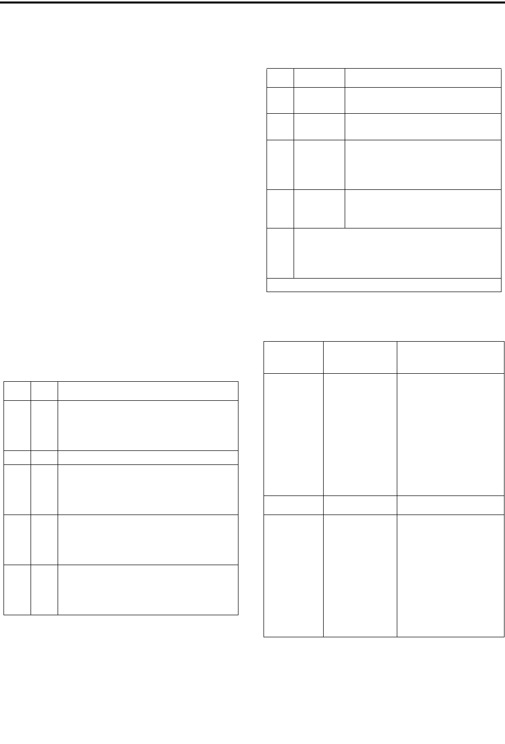
Table 7-1 BASIC BOARD SWITCH SETTINGS
S
w Sec Description
S1 1
2
3
4
AFSK Data Receive Secondary Line
AFSK Data Receive Main Audio Input
Voice from main board
AFSK Data Receive from PCM
S2 Resets the microprocessor
S3 1
2
3
4
AFSK Secondary Transmit Data +
AFSK Secondary Transmit Data -
Digital Secondary Transmit Data ground
Digital Secondary Transmit Data signal
S4 1
2
3
4
Digital Secondary Receive Data signal
Digital Secondary Receive Data ground
AFSK Secondary Receive Data +
AFSK Secondary Receive Data -
S5 1
2
3
4
Bit 0 - Alignment Test Switch
Bit 1
Bit 2
Bit 3
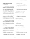
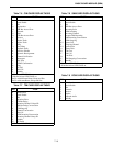
Table 7-2 BASIC BOARD JUMPER
PLACEMENT
JU Pin Description
J24 1 to 2
2 to 3*
Not Used
Normal
operation
J27 1 to 2
2 to 3*
Not Used
No ALC
P33 1 to 2*
3 to 4*
5
6
No personality card attached
No personality card attached
open
open
J36 1 only*
1 to 2
2 to 3
Not used
-48V E-lead operation
-15V E-lead operation
J14
J15
J21
J22
Jumper pin 1 to 2 for high impedance ground path
for split 600 ohm inputs and outputs. Leave open
if no ground path desired.
* Normal setting.
Table 7-3 BACKPLANE PIN-OUTS
Backplane
P34 to P45 Description
Wire Harness
P-Odd J1,3,5,7
pin 25
pin 26
pin 27
pin 28
pin 29
pin 30
pin 31
pin 32
Test Tx Data
Test Rx Data
Sec Rx +
Sec Rx -
EA lead
EB lead
main Rx
Audio, Tip +
Main Rx
Audio, Ring _
pin 1
pin 2
pin 3
pin 4
pin 5
pin 6
pin 7
pin 8
RxS+
RxS-
EA
EB
RxA+
RxA-
pin 1
pin 2
pin 3
pin 4
pin 5
pin 6
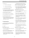
P-Even J2,4,6,8
pin 57
pin 58
pin 59
pin 60
pin 61
pin 62
pin 63
pin 64
Alarm
Alarm
Sec Tx +
Sec Tx -
MA lead
MB lead
Main Tx
Audio +
Main Tx
Audio -
pin 1
pin 2
pin 3
pin 4
pin 5
pin 6
pin 7
pin 8
TxS+
TxS-
MA
MB
TxA+
TxA-
pin 1
pin 2
pin 3
pin 4
pin 5
pin 6