


DISPATCH INTERFACE MODULE (DIM)
11-2
11.2.3 E-LEAD SELECTION
If the PTT from the console is an open contact
relay, either of the above options for J36 may be used.
If the PTT is a closure to ground with a pull-up
resistor to a positive voltage, J36, pin 2 should be
connected to ground without connection to pin 1 or
pin 3.
11.2.4 DIM BACKPLANE EXTERNAL
CONTACTS
See Backplane Section 23 for pinouts on the shelf
backplane and wire harness pinouts.
11.3 DIM ALIGNMENT SPECIFICATION
11.3.1 PRE-ALIGNMENT
The DIM is pre-aligned with the Basic Board
Module alignment procedures (Refer to Section 7.3).
The tone remote personality card should be removed
and P33 jumpered accordingly for the proper pre-
alignment of the module (Refer to Table 11-2).
11.3.2 PRE-ALIGNMENT WITH TONE REMOTE
PERSONALITY CARD
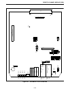
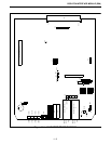
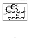
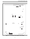
Set the module for pre-alignment by referring to
Table 11-1, Alignment Points Diagram Figure 7-2, and
Figure 11-1.
1. Set the card Tone Remote PTT level alignment:
a. Inject 2175 Hz
±1 Hz at 0 dBm into EQU of Rx
input J1.
b. Open S1 (Sections 1, 2, 3 and 4).
c. Set S5 for Test 1 (Open section 1, close section 2,
3 and 4).
d. Reset the module, press S2 and release.
5. Main Rx audio level from J1:
a. Setup for alignment as in Step 1.
b. Adjust R41 to -6 dBm
±0.5 dB at J11.
3. Tone Remote Personality Card:
a. Adjust R207 for a minimum at EP221. (Should
be < -15 dBm.)
b. Adjust R228 for 0 dBm
±0.5 dB at EP224.
c. Adjust R236 for a peak level at EP225.
d. Adjust R272 for a peak level at EP227.
e. Verify EP228/EP229 are high (> 4.5V).
f. Reduce the level of the 2175 Hz tone until EP228
goes low (< 0.8V). Verify the level of the 2175 Hz
tone is -10 dBm
±2 dB.
g. Verify that EP229 is still high ( > 4.5V).
h. Reduce the level of the 2175 Hz tone until EP229
goes low (< 0.8V). Verify the level of the 2175 Hz
tone is -40 dBm
±2 dB.
i. Change the frequency and level of the input tone
to 1004 Hz at -12 dBm.
j. Verify that the level at J11 is -6 dBm
±1 dB.
k. Verify that the level at EP221 is -6 dBm
±1 dB.
l. Verify that the level at TP5 is -6 dBm
±1 dB.
m.Adjust R211 for -12 dBm
±1 dB at EP222.
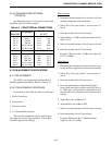
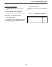
Table 11-3 BACKPLANE PLACEMENT
Backplane
P34 to P45
Description
Wire Harness
J1,3,5,7
pin 27
pin 28
pin 29
pin 30
pin 31
pin 32
Sec Rx +
Sec Rx -
EA lead
EB lead
Pri Rx Audio+
Pri Rx Audio-
pin 1
pin 2
pin 3
pin 4
pin 5
pin 6
RxS+
RxS-
EA
EB
RxA+
RxA-
J2,4,6,8
pin 59
pin 60
pin 61
pin 62
pin 63
pin 64
Sec Tx +
Sec Tx -
MA lead
MB lead
Pri Tx Audio+
Pri Tx Audio-
TxS+
TxS-
MA
MB
TxA+
TxA-
pin 1
pin 2
pin 3
pin 4
pin 5
pin 6