ARCHITECTURE
3-4
3.3.3 VOICE BUS
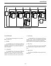
The following are descriptions of voice buses.
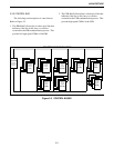
Refer to Figure 3-4.
1. VTM Bus
A 2.048 MHz Pulse Code Modulated (PCM) bus
containing 32 slots of tones or voice the modules use
to indicate call progress to an end user by means of
audio information.
2. Tx PCM BUS
A 2.048 MHz Pulse Code Modulated (PCM) bus
containing 32 slots. Audio received from the RF
channel is transmitted on these slots by the channel
modules and received by the other system modules.
3. Rx PCM Bus
A 2.048 MHz Pulse Code Modulated (PCM) bus
contains 32 slots. Audio is transmitted from the other
system modules to these slots and received by the
channel modules to be transmitted on the RF channel.
4. Master Sync
Provides the synchronization signal for the PCM
bus communication to begin the frame of 32 PCM
slots.
5. Master Clock
Provides the 2.048 MHz clocking signal for the
PCM buses.
Figure 3-4 VOICE BUSES
CIMs CCMs
VOICE
TONE
MODULE
VTM
CONVENTIONAL
CHANNEL
MODULE
INTERFACE
CHANNEL
MODULE
VOICE TONE MODULE BUS
MASTER SYNC / MASTER CLOCK
DISPATCH
MODULE
CHANNEL
DCMs
TELEPHONE
MODULE
INTERFACE
TIMs
NETWORK
SYSTEM
MODULE
SNMs
WIDE
MODULE
AREA
WA Ms
LOGGING
MODULE
ENCODER
LEMs
TX/RX PCM


