


8-1
CHANNEL INTERFACE MODULE (CIM)
SECTION 8 CHANNEL INTERFACE MODULE (CIM)
8.1 DESCRIPTION
Refer to 3000 Series Switch Service Information
manual, Part No. 001-3139-102, for the component
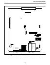
layout, parts list and schematic. Refer to Figure 7-1
for the Basic Board block diagram. The Channel Inter-
face Module (CIM) connects the Switch to the Multi-
Net and LTR Repeaters. Each repeater has a CIM that
monitors and controls the repeater through logic
signaling.
8.1.1 REPEATER SIGNALING
The CIM uses one of three methods to exchange
control information with its repeater: RS-232 lines,
Audio Frequency Shift Keying (AFSK) data on a
separate audio path, or by AFSK data in a blank and
burst mode on the voice audio path.
8.1.2 REPEATER CONTROL
The CIM controls the repeater with restart,
enable and disable, executes requests to read and write
to the repeater's memory, and tells the repeater
transmit code, hang or send turnoff. The CIM
receives confirmation of all requests made to the
repeater and sends information the repeater receives.
8.1.3 VOICE CONNECTION
The CIM provides a 4-Wire 600 ohm balanced
voice connection to the repeater, converts audio to and
from Pulse Code Modulation (PCM), transmits and
receives on the PCM buses, and controls voice audio
gating to and from the repeater.
8.1.4 INTERNAL COMMUNICATION
The CIM uses the Intra-Terminal Data Bus (IDB)
to communicate to other modules and send messages
to and receive messages from the Call Processor that
controls its actions.
The status of the CIM/Repeater combination is
determined by the other modules by what the CIM
transmits on the Channel Status Bus (CSB). The other
modules monitor the CSB and determine if a CIM has
the appropriate group and status for the type of
communication the module requires.
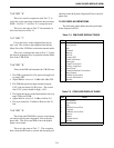
8.2 CIM SETUP PROCEDURE
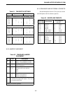
8.2.1 SWITCH SETTINGS
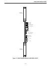
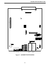
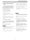
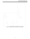
Refer to Figure 8-1 for Alignment Points
Diagram.
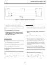
Command and Control Communication
The command and control communication to the
Multi-Net Logic Module or the Repeater Interface
Module may take place by several different forms.
The form chosen is typically dependent upon the
location of the repeaters to the CIM equipment.
1. If the location is within 200 feet, it is suggested that
the communication take place digitally on the
secondary line.
2. If the location is greater than 200 feet, the commu-
nication taking place uses the Audio Frequency
Shift Keyed (AFSK) modems. This may take place
on the Secondary lines if the appropriate facilities
are available; i.e. 4-Wire leased line or microwave
link.
3. The AFSK may be done using the blank and burst
mode on the Main audio lines. This is typically
used when the link is by leased lines or microwave,
but the number of lines available does not allow for
the use of the secondary line connections. (This has
a low level burst of data (100 ms) at the end of trans-
missions.)