


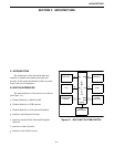

SYSTEM RACK
4-2
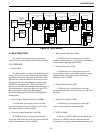
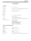
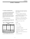
4.1.3 TWO SHELF POWER SUPPLY
The Power Supply has a 115/230V AC 50/60 Hz
input and 4 continuous duty outputs as follows:
+5V DC 24A.
-5V DC 6A.
+12V DC 3A.
-12V DC 5A.
The power supply can handle 2-shelves and has
the following connections:
4 separate +5V 2A connections.
2 separate -5V connections.
2 separate +12V connections.
2 separate -12V connections.
6 separate ground connections.
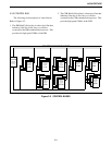
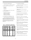
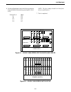
4.1.4 POWER SUPPLY REDUNDANT PLATE
The power supply drawer can be made redun-
dant by the use of the redundant diode plate (PN 023-
3039-553). The redundant plate allows two power
supply drawers to share the load via diodes. One of the
power supply drawers may be removed and the
remaining drawer will supply the full load. (See
Figure 4-10.)
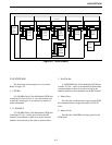
4.1.5 VOLTAGE ADJUSTMENTS
See Figure 4-10 for location of components and
Table 4-2 for wire connections.
1. Connect a voltmeter to U1, pin 76 on an RVM (DO
NOT use an extender card).
2. Adjust the +5V pot on the power supply for a
reading of 5.1V.
3. If +5.1V cannot be obtained, change R84 to a 5.6k
ohm 1/4W resistor.
4.1.6 REDUNDANT SUPPLY ADJUSTMENTS
See Figure 4-10 for location of components and
Table 4-2 for wire connections.
1. Remove the AC voltage to one of the supplies.
2. Connect a voltmeter to U1, pin 76 on an RVM (DO
NOT use an extender card).
3. Adjust the +5V pot for a reading of 5.1V. (If +5.1V
cannot be obtained, change R84 to a 5.1k ohm 1/4W
resistor.)
4. Connect a voltmeter to output of CR3 and verify
that the -5V line is -4.8V to -5.2V. (If not, make
R68 lower to raise voltage.)
5. Remove the AC voltage to the adjusted supply and
connect AC voltage to the other power supply.
6. Connect a voltmeter to U1, pin 76 on an RVM (DO
NOT use an extender card).
7. Adjust the +5V pot for a reading of 5.1V. (If +5.1V
cannot be obtained, change R84 to a 5.1k ohm 1/4W
resistor.)
8. Connect a voltmeter to output of CR3 and verify
that the -5V line is -4.8V to -5.2V. (If not, make
R68 lower to raise voltage.)
4.1.7 VERIFY FAN AIR FLOW DIRECTION
1. Connect the power cables to a 110V AC source.
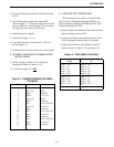
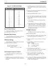
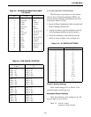
Table 4-2 POWER SUPPLY CONNECTIONS
TB1 Wire
No.
Color From
Term 1
Term 2
Term 3
W1
W1
W1
Blk
Wht
Grn
AC (Hot)
AC (Ntrl)
AC (Gnd)
Line
Line
Line
TB2
Term 1
Term 2
Term 3
Term 4
Term 5
Term 6
Term 7
Term 8
Term 9
W1
W2
W6
NC
W7
W4
W5
W3
W8
Red
Red
Blu
Blu
Blu
Wht
Grn
Blu
+5V
+5V
Gnd
Gnd
+12V
-12V
-5V
Gnd
F1
F1
Gnd
Gnd
F3
F4
F2
Gnd