


18-1
VOICE TONE MODULE (VTM)
SECTION 18 VOICE TONE MODULE (VTM)
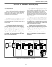
18.1 DESCRIPTION
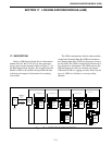
The Voice Tone Module (VTM) provides tone
and voice message to modules that indicate call
progress to the users.
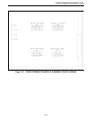
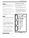
The VTM contains 8-fixed slots of digitized
PCM audio messages stored in PROMs that are 4
seconds in length and repeat continuously on the VTM
PCM bus of the Switch (see Table 18-3). The start of
the message is indicated in the transmission so
modules can present the audio message to the user
from the beginning of the message. There may be up
to four VTMs within a system, depending upon the
messages required.
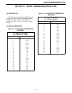
18.2 SETUP PROCEDURE
18.2.1 VTM JUMPER PLACEMENT
18.2.2 VTM SWITCH SETTINGS
18.3 ALIGNMENT SPECIFICATIONS
No alignment is required for the VTM to operate
in the system. However, panel jack output level is
adjustable. The S1 switch setting must be correct for
the starting slot number. Use S2 to select a voice or
tone message.
1. Insert a "butt-set" in the front panel jack.
2. Adjust R22 for a comfortable listening level.
3. If a tone is selected, set the level at TP1, 9 dB lower
than the level on U24, pin 2 for the proper level to
the "butt-set".
NOTE: Revision 2 or earlier should have the line from
P1, pin 1 to R25 cut. Revision 3 or later should have
Jumper on -pin 1 only.
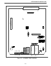
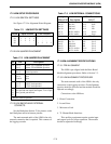
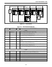
Table 18-1 VTM BOARD JUMPER
PLACEMENT
JU Pin Description
J11
J12
2 to 2*
3 to 3*
Selects 27256 EPROM operation
1 to 1
3 to 3
Selects 27128 EPROM operation
1 to 1
3 only
Selects 2764 EPROM operation
J20 1 to 2 Transmit PCM Bus line
2 to 3* VTM PCM Bus line
*Setting for Normal operation.
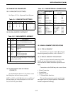
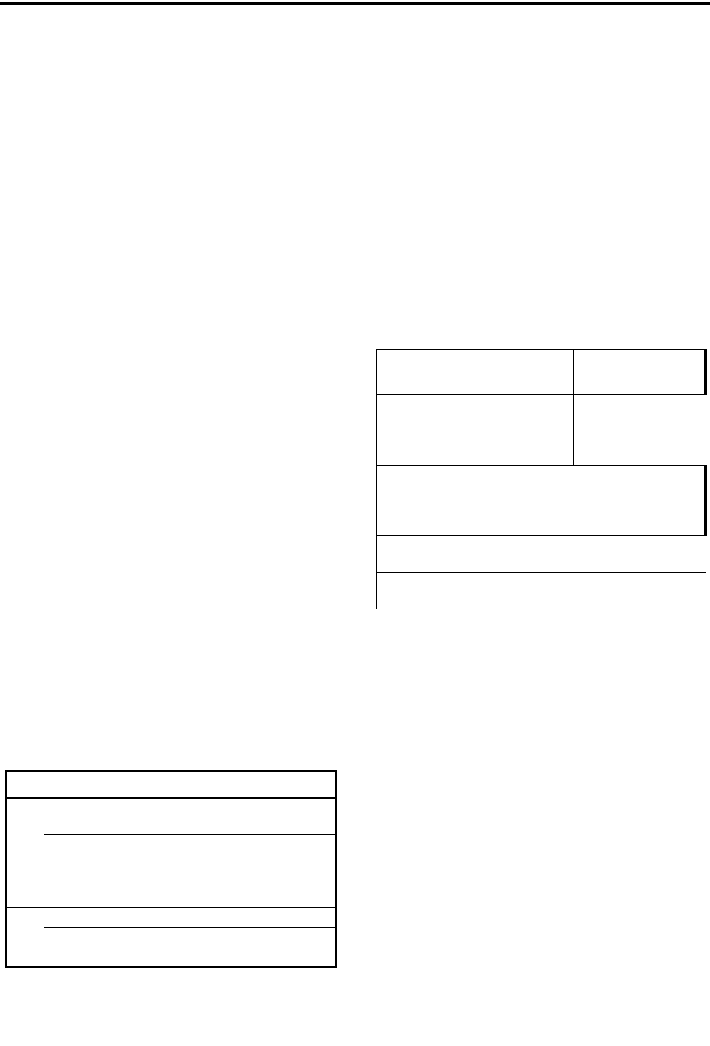
Table 18-2 VTM BOARD SWITCH SETTINGS
Switch
VTM starting
slot
Sections
1 2
S1 0*
8**
16
24
Closed
Open
Closed
Open
Closed
Closed
Open
Open
S2 - Monitor Switch. A front panel,
16-position switch with two positions for
each slot. The switch selects the slot to
be monitored at the front panel jacks.
S3 - Reset. Normally open, press to reset.
Momentary switch to reset module.
* VTM 1
** VTM 2.