


WIDE AREA MODULE (WAM)
19-2
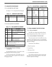
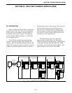
19.2 WAM SETUP PROCEDURE
19.2.1 WAM SWITCH SETTINGS
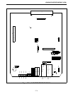
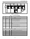
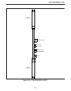
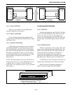
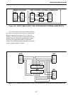
See Figure 19-2 for Alignment Points Diagram.
19.2.2 WAM JUMPER PLACEMENT
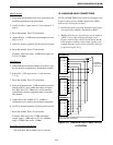
19.2.3 WAM BACKPLANE EXTERNAL
CONTACTS
See the Backplane Section 23 for pinouts on the
shelf backplane and wire harness pinouts.
NOTE: An ECO to the WAM allows for an additional
M-Lead output pair to the Backplane on TxS+ and
TxS- (P34 to P45, pins 59/60).
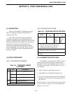
19.3 WAM ALIGNMENT SPECIFICATIONS
19.3.1 PRE-ALIGNMENT
The WAM is pre-aligned with the Basic Board
Module alignment procedures; refer to Section 7.3.
19.3.2 WAM ALIGNMENT PROCEDURE
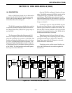
There are several external connections for the
WAM, and good alignment practice should be
followed and the module should be adjusted accord-
ingly.
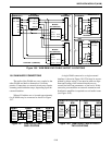
Connections to the WAM may take several forms:
• Direct Connection
• Leased Lines
• Microwave Link
• T1 Channel Bank Interfaces
This ancillary equipment requires certain input
and output levels for proper operation. The module
should be adjusted accordingly.
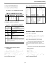
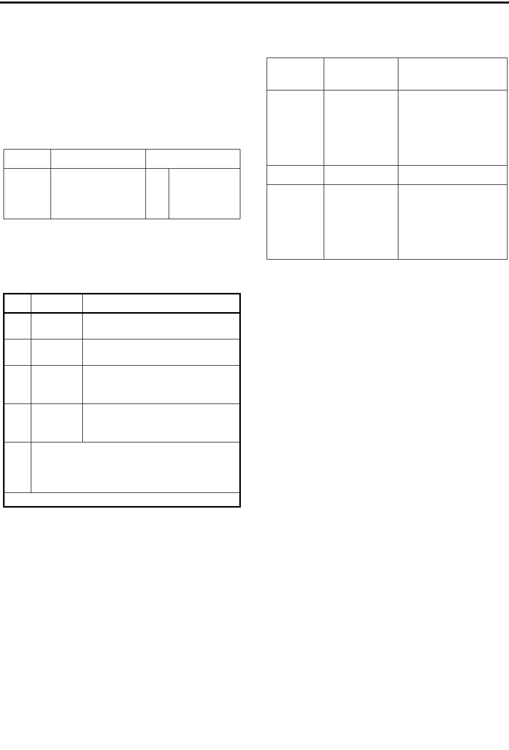
Table 19-1 WAM SWITCH SETTINGS
Switch Open Sections Close Sections
S1
S3
S4
S5
1
1
1
-
2
2
2
-
-
3
3
-
4
4
4
-
-
-
-
1
-
-
-
2
3
-
-
3
-
-
-
4
Table 19-2 WAM JUMPER PLACEMENT
JU Pin Description
J24 1 to 2
2 to 3*
Selects 27512 EPROM operation
Selects 27256 EPROM operation
J27 1 to 2
2 to 3*
Not used
Normal operation
P33 1 to 2
3 to 4
5 and 6
Jumpered
Jumpered
open
J36 1 only
1 to 2
2 to 3
Not used
-48V E-lead operation
-15V E-lead operation
J14
J15
J21
J22
Jumper pin 1 to 2 for high impedance ground path
for split 600 ohm inputs and outputs. Leave open if
no ground path desired.
* Indicates normal operation.
Table 19-3 WAM EXTERNAL CONNECTIONS
Backplane
P34 to P45
Description
Wire Harness
J1,3,5,7
pin 27
pin 28
pin 29
pin 30
pin 31
pin 32
Sec Rx +
Sec Rx -
EA lead
EB lead
Pri Rx Audio+
Pri Rx Audio-
pin 1
pin 2
pin 3
pin 4
pin 5
pin 6
RxS+
RxS-
EA
EB
RxA+
RxA-
J2,4,6,8
pin 59
pin 60
pin 61
pin 62
pin 63
pin 64
Sec Tx +
Sec Tx -
MA lead
MB lead
Pri Tx Audio+
Pri Tx Audio-
TxS+ (MA2)
TxS- (MB2)
MA (MA1)
MB (MB1)
TxA+
TxA-
pin 1
pin 2
pin 3
pin 4
pin 5
pin 6