


TELEPHONE INTERFACE MODULE (TIM)
14-24
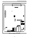
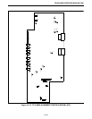
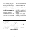
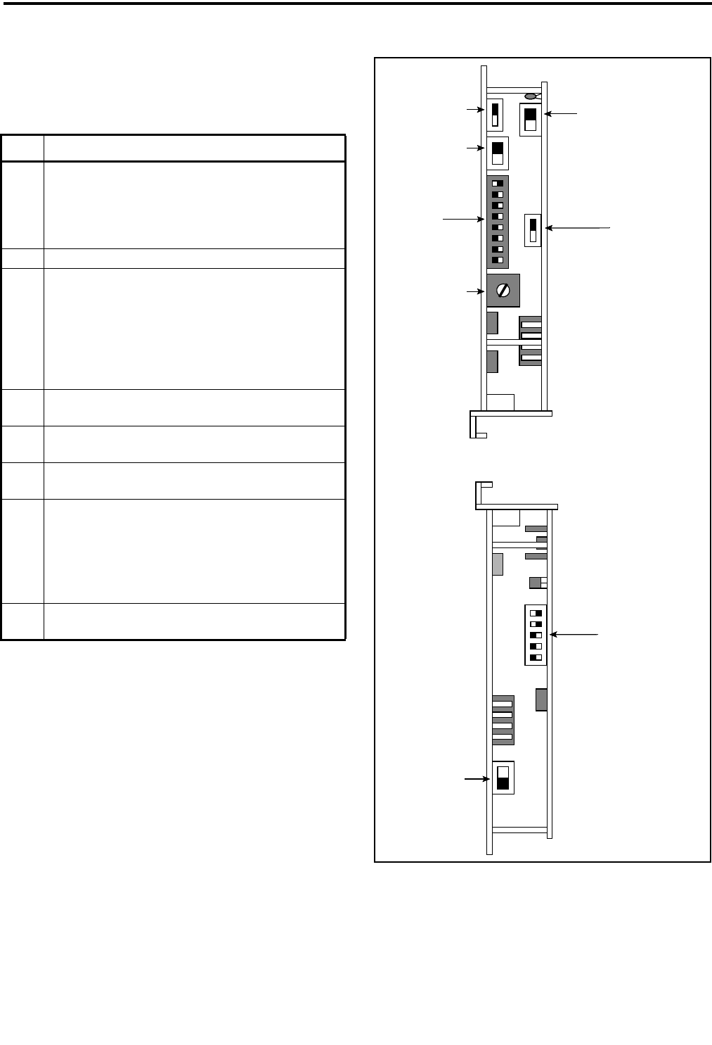
14.11.3 SWITCH SETTINGS ON 6132A (DID AP-
PLICATIONS)
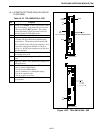
Figure 14-23 TELLABS 6132A - DID
Table 14-10 TELLABS 6132A - DID
Sw Purpose
S14 Initially set to NORM. If the E-Lead (Green LED)
stays on constantly, or the termset does not answer
in-dial, place S14 in REV position. This switch
reverses the battery polarity presented to the CO
from the Termset in DID applications.
S5 Place in 2W. This switch determines the interface.
S4 To get started, set to 900, with all capacitors in. Set
to variable and adjust R38 when performing the
actual balance. This balance network allows 600,
900 or variable resistor (2k) resistive balance. Also,
5 capacitors ranging from .002 µF to .032 µF in
octaves (i.e. .064 µF total capacitance) provide for a
capacitive balance.
R38 This potentiometer controls the resistive balance in
the variable mode of S4.
S11 Set to B. This switch swaps roles of E-Lead and M-
Lead.
S12 Supervisory Mode. Set to RB (Reverse Battery) for
DID applications.
S15 Set to a = inv, b = inv, c = d = e = off.
'a' sets up inverted E&M inputs.
'b' sets up inverted E&M outputs.
'c' sets up continuous (vs. interrupted ringing.
'd' sets up no ring-back tone.
'e' sets up no pulse correction.
S3 Set to 600. This switch provides 2W port terminat-
ing impedance.
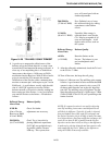
c = d = e = off
b = inv
a = inv
S15
RB (REVERSE BURST)
B
S11
BOTTOM UP
600
S3
S12
TOP DOWN
R38
ALL CAPS ON
900
S4
2W
S5
NORM
S14