


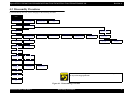


Epson STYLUS NX100/NX105/SX100/SX105/TX100/TX101/TX102/TX103/TX105/TX106/TX109/ME 300 Revision A
DISASSEMBLY/ASSEMBLY Removing the Circuit Boards 65
Confidential
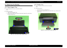
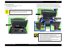
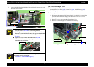
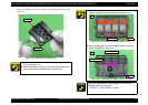
Buttons
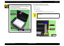
1. Remove the Button Power and the Button OP from the Panel Cover.
2. Remove the LED Lens from the Panel Cover.
Figure 4-19. Removing the Buttons
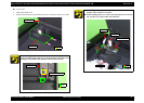
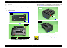
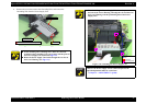
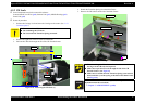
4.4.2 Main Board
Parts/Components need to be removed in advance:
Scanner Stand/Cover Wire (p 60), Scanner Unit (p 62), Middle Housing (p 63)
Panel Unit (p 64), Hopper (p 72)
Removal procedure
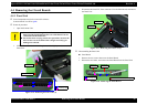
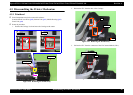
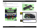
1. Remove all the cables and FFCs connected to the Main Board.
Figure 4-20. Removing the Main Board (1)
When installing the Panel Board, align the positioning hole of
the Panel Board with the dowels of the Panel Cover. (See
Fig.4-18)
When installing the Panel Unit, align the positioning holes of the
Middle Housing with the dowels of the Panel Cover, then secure
them with four hooks. (See
Fig.4-16, Fig.4-19.)
Button PowerButton OP LED Lens
Panel Cover
Dowel
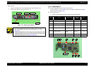
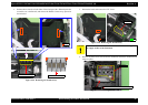
CN No
Cable
Cable Color
Connector
Color
Pins
J2 Panel FFC --- Black 10
J3 Power Supply Unit cable Gray Brown 3
J4 Scanner FFC --- Black 12
J5 Scanner Motor Cable Black,Brown,
Orenge,Yellow
White 4
J6 PF Motor Cable Red,
Black
White 2
J7 CR Motor Cable Gray,
Black
Brown 2
J8 Head FFC --- Black 21
J9 FFC --- Black 17
Main Board
J3J6 J7
J2J4J5J8J9