


Epson STYLUS NX100/NX105/SX100/SX105/TX100/TX101/TX102/TX103/TX105/TX106/TX109/ME 300 Revision A
DISASSEMBLY/ASSEMBLY Disassembling the Printer Mechanism 83
Confidential
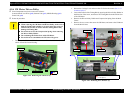
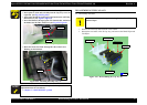
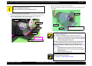
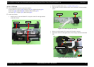
3. Remove the screw that secures the Bracket.
4. Release the Bracket from the dowels of the Lower Housing, and remove the
Bracket and the PF Motor while pulling out the PF Motor Cable (see
Fig.4-67.) through the hole of the Lower Housing.
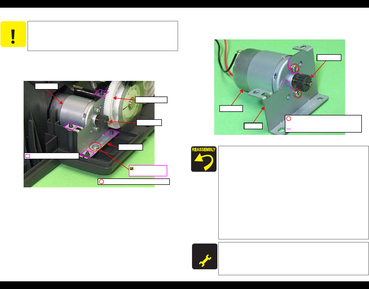
Figure 4-69. Removing the PF Motor (3)
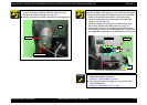
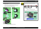
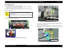
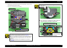
5. Remove both the screws that secure the PF Motor.
6. Remove the PF Motor pulling out the shaft of the motor through the notch of
the Bracket.
Figure 4-70. Removing the PF Motor (4)
C A U T I O N
Do not damage the PF Roller Gear.
Do not damage the Pinion Gear.
Be careful of not to break the soldered portions.
Positioning Hole and Dowel
Bracket
PF Motor
PF Roller Gear
Pinion Gear
SCREW M3x8 P-TITE (5±0.5kgfcm)
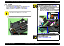
Screw it with the
Grounding Wire.
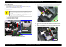
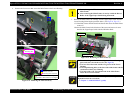
When installing the PF Motor, insert the black cable over the
red one. (See
Fig.4-70.)
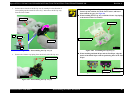
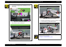
Install the Grounding Spring as follows: (See Fig.4-68.)
1. Insert the tip of the spring to the hole of the Lower Housing.
2. Attach the eyes of the spring to the hook of the Main Frame
and that of the Bracket to secure it.
Before securing the Bracket, align the four positioning holes of
it with the four dowels of the Lower Housing. (See
Fig.4-69.)
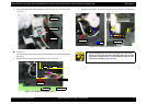
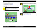
Don not damage the PF Roller Gear and the Pinion Gear.
Route the PF Motor Cable following the procedure below. (See
Fig.4-67.)
1. When pulling out the cable from the hole of the Lower
Housing, give the cable some slack to prevent breaking the
soldered portions.
2. Route the cable through the rib.
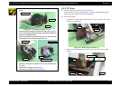
A D J U S T M E N T
R E Q U IR E D
Whenever the PF Motor removed/replaced, the required
adjustments must be carried out.
• Chapter 5 “ ADJUSTMENT” (p.100)
PF Motor
Bracket
Pinion Gear
SCREW SEMS M2.6x3.5 PAN HEAD+
(3.5±0.25kgfcm)
Notch