


Epson STYLUS NX100/NX105/SX100/SX105/TX100/TX101/TX102/TX103/TX105/TX106/TX109/ME 300 Revision A
DISASSEMBLY/ASSEMBLY Disassembling the Printer Mechanism 76
Confidential
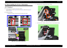
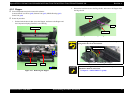
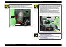
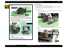
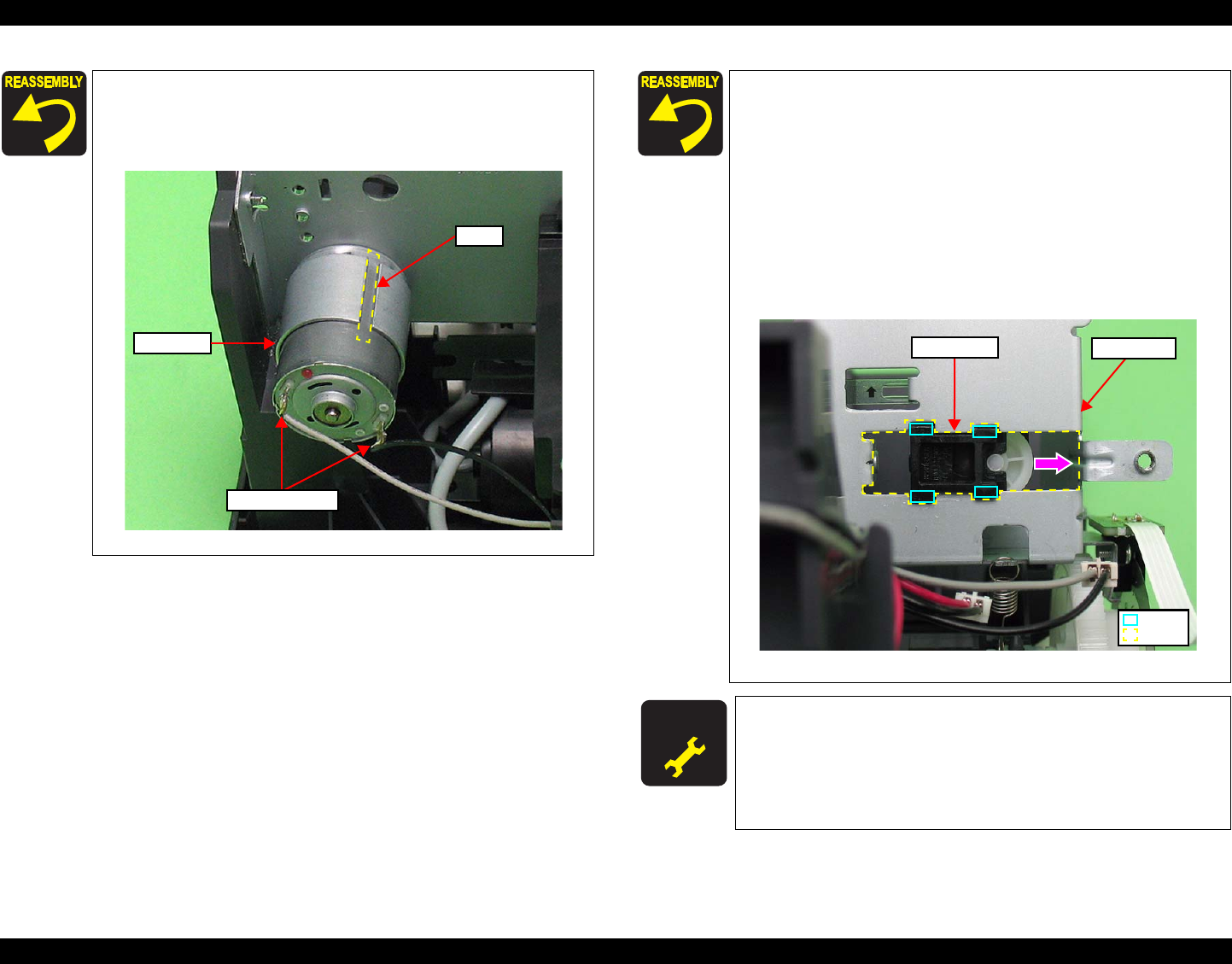
Route the CR Motor cable through the four hooks and the two
grooves of the Lower Housing with some slack to prevent
breaking the soldered portions. (See
Fig.4-45.)
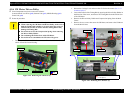
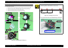
Be sure to install the CR Motor with the groove facing upward.
Figure 4-47. Installing the CR Motor
CR Motor
Groove
Soldered Portions
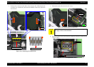
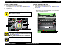
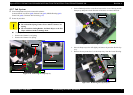
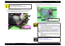
When installing the Timing Belt to the Pinion Gear of the CR Motor
follow the procedure below taking care not to twist the Timing Belt.
1. Align the hooks of the Driven Pulley with the hole of the Main
Frame, and install the Driven Pulley to the Main Frame.
2. Attach the Timing Belt to the Driven Pulley with toothed side
facing inward. (See
Fig.4-46
.)
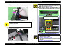
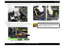
3. Install the Compression Spring between the protrusion of the
Driven Pulley and that of the Main Frame. (See
Fig.4-46
.)
4. Slide the Driven Pulley to the CR Motor (in the direction of the
arrow) taking care not to let the Timing Belt come off, and install
the Timing Belt to the Pinion Gear of the CR Motor. (See
Fig.4-46
.)
Figure 4-48. Installing the Driven Pulley
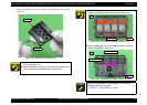
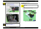
A D J U S T M E N T
R E Q U IR E D
Whenever the CR Motor is removed/replaced, the required
adjustments must be carried out.
• Chapter 5 “ ADJUSTMENT” (p.100)
After replacing the Driven Pulley, be sure to perform the
required lubrication.
• Chapter 6 “ MAINTENANCE” (p.108)
Main Frame
Hole
Driven Pulley
Hook