


Epson STYLUS NX100/NX105/SX100/SX105/TX100/TX101/TX102/TX103/TX105/TX106/TX109/ME 300 Revision A
DISASSEMBLY/ASSEMBLY Disassembling the Printer Mechanism 85
Confidential
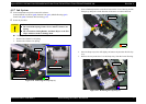
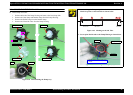
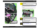
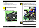
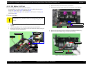
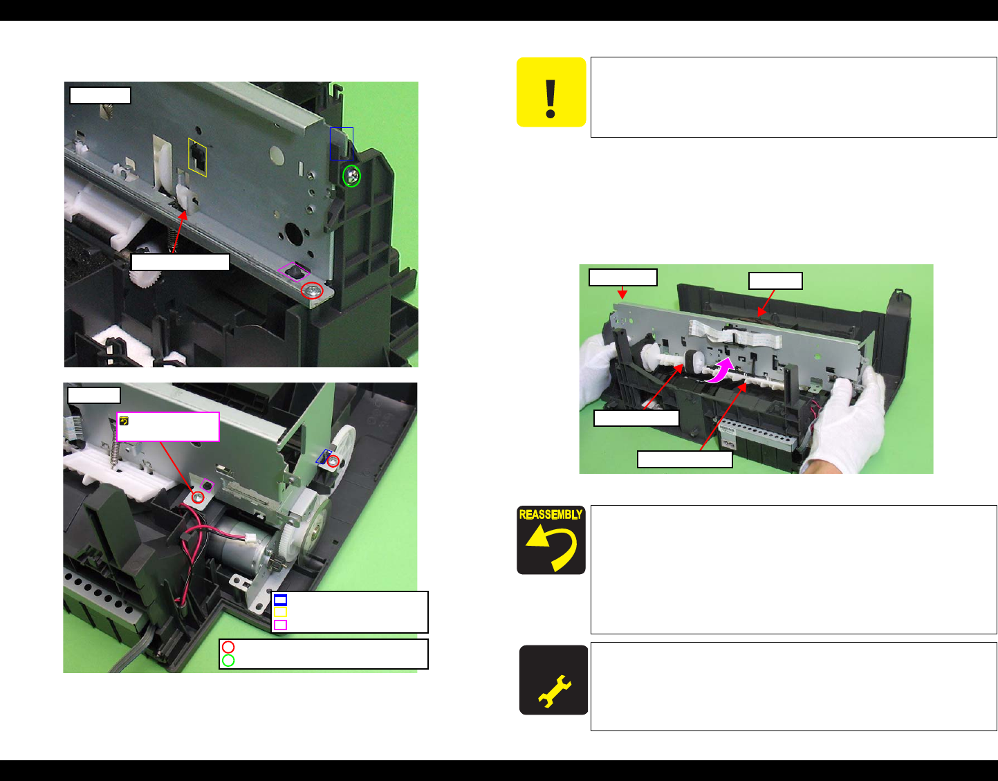
6. Remove the four screws that secure the Main Frame to the Lower Housing.
Figure 4-74. Removing the Main Frame (4)
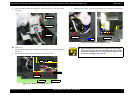
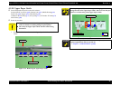
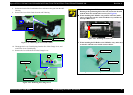
7. Remove the Main Frame, the Carriage, and the Upper Paper Guide from the
Lower Housing following the procedure below. (See
Fig.4-74, Fig.4-75.)
1.Lift the Main Frame until the dowel and the rib that secure the Main Frame
comes off.
2.Rotate the Main Frame in the direction of the arrow and remove it not to
interfere the Upper Paper Guide with the LD Roller Shaft.
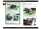
Figure 4-75. Removing the Main Frame (5)
Rear Left
Positioning Hole and Dowel
Rib and Groove
Hook of ASF Unit
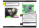
SCREW M3x8 P-TITE (5±0.5kgfcm)
SCREW S-TIGHT M3x6 (7.5±0.5kgfcm)
Screw it with the
Grounding Wire.
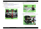
Front Right
Lever Pick Clutch
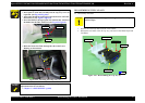
C A U T I O N
Do not damage the PF Scale and the Lever Pick Clutch with the
Main Frame.
After removing the Main Frame, do not lay it with the Driven
Roller of the Upper Paper Guide facing downward.
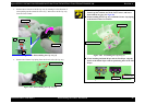
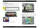
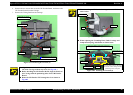
When installing the Main Frame, align it with the following
parts, and secure it with the screws. (See
Fig.4-74.)
• The two ribs of the frame and the two grooves of the Lower
Housing
• The two positioning holes on the lower side of the frame and the
two dowels of the Lower Housing
• The hook of the ASF Unit and the hole of the Main Frame
above the Lever Pick Clutch
A D J U S T M E N T
R E Q U IR E D
Whenever the Main Frame is removed/replaced, the required
adjustments must be carried out.
• Chapter 5 “ ADJUSTMENT” (p.100)
Main Frame
LD Roller Shaft
Upper Paper Guide
Carriage