


Epson STYLUS NX100/NX105/SX100/SX105/TX100/TX101/TX102/TX103/TX105/TX106/TX109/ME 300 Revision A
DISASSEMBLY/ASSEMBLY Removing the Circuit Boards 67
Confidential
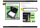
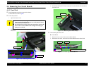
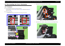
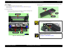
4. Remove the screw that secures the Grounding Wire, and remove the
Grounding Wire from the Power Supply Unit.
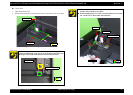
Figure 4-24. Removing the Power Supply Unit
When installing the Grounding Wire, make sure that the
terminal of the Grounding Wire gets contact with the plate of
the Power Supply Unit as shown in
Fig.4-24.
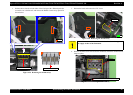
Route the Power Supply Unit Cable through the two ribs of
the Lower Housing. (See
Fig.4-23.)
SCREW M3x8 P-TITE (5±0.5kgfcm)
Terminal
Grounding Wire
Power Supply Unit
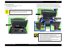
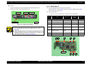
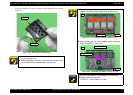
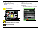
When installing the Power Supply Unit, insert its protrusion to
the hole of the Lower Housing, and align the rib and dowel of
the Lower Housing with the positioning hole of the Power
Supply Unit.
Figure 4-25. Installing the Power Supply Unit
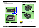
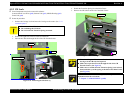
A D J U S T M E N T
R E Q U IR E D
Whenever the Power Supply Unit is removed/replaced, the
required adjustments must be carried out.
• Chapter 5 “ ADJUSTMENT” (p.100)
Dowel
Positioning Hole
Protrusion
Rib