


Epson STYLUS NX100/NX105/SX100/SX105/TX100/TX101/TX102/TX103/TX105/TX106/TX109/ME 300 Revision A
DISASSEMBLY/ASSEMBLY Disassembling the Printer Mechanism 88
Confidential
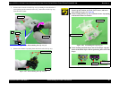
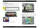
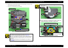
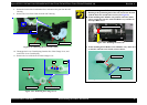
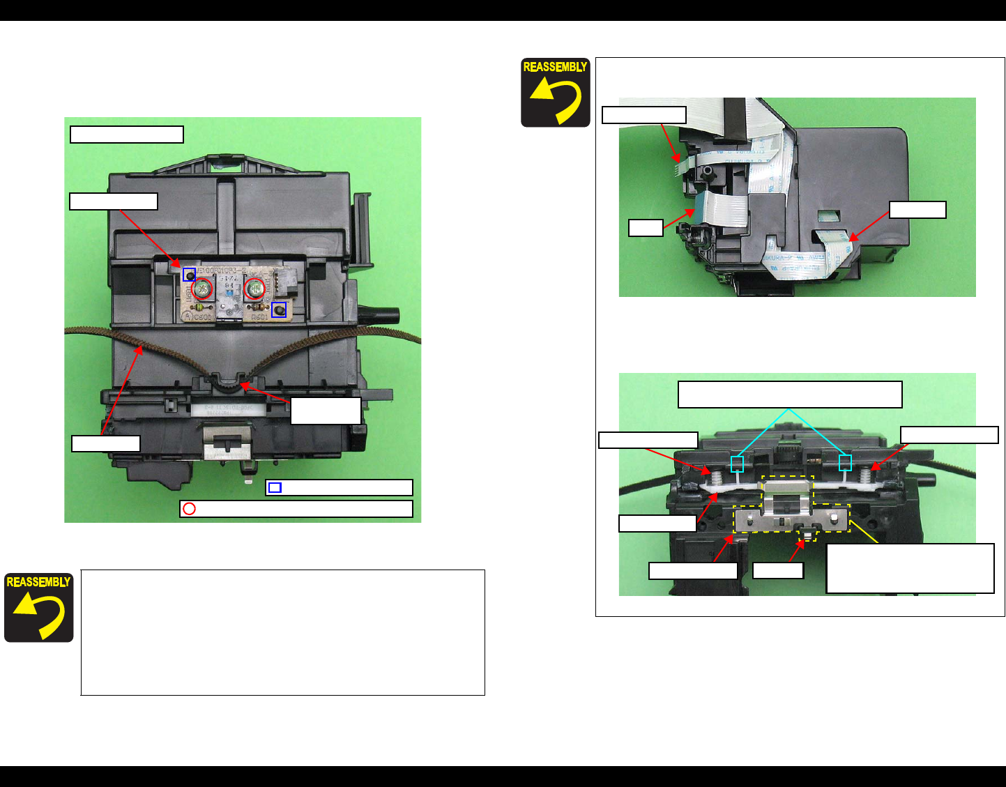
6. Remove the two screws that secure the CR Encoder Board, and remove the
CR Encoder Board from the Carriage.
7. Remove the Timing Belt from the Carriage.
Figure 4-81. Removing the CR Unit (4)
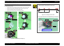
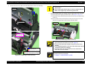
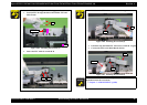
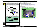
Align the toothed side of the Timing Belt with the same shaped
rib of the Carriage without any twist. (See
Fig.4-81.)
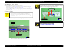
Before installing the CR Encoder Board, align the dowels of
the Carriage with the positioning holes of the CR Encoder
Board.
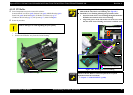
Route the CR Encoder FFC through the rib as shown in
Fig.4-80.
CR Sensor Assy
Backside of Carriage
Timing Belt
Toothed rib
of Carriage
Positioning Hole and Dowel
M2x6 P-TIGHT BIND HEAD (3±0.25kgfcm)
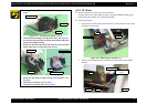
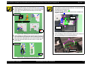
When installing the FFC to the Carriage, route the FFC as
shown below.
Figure 4-82. Installing the CR Unit (1)
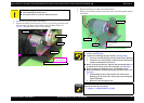
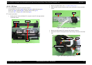
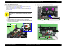
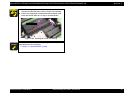
When replacing the Grounding Plate, Guide Carriage and
Compression Spring, install them as shown below.
Figure 4-83. Installing the CR Unit (2)
FFC
CR Encoder FFC
Head FFC
Insert the protrusion of the plate to
the hole of the Carriage, then align
the dowels of the Carriage with the
positioning holes of the plate.
Grounding Plate
Guide Carriage
Compression Spring
Protrusion
Compression Spring
Secure two hooks of the Guide Carriage by
attaching them on the two holes of the Carriage.