


Epson STYLUS NX100/NX105/SX100/SX105/TX100/TX101/TX102/TX103/TX105/TX106/TX109/ME 300 Revision A
DISASSEMBLY/ASSEMBLY Disassembling the Printer Mechanism 70
Confidential
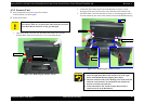
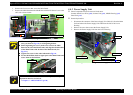
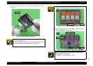
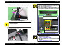
7. Remove the Head FFC from the connector of the Printhead, and remove the
Printhead.
Figure 4-32. Removing the Printhead (7)
When installing the FFC, route it through objects as shown in
Fig.4-27 and Fig.4-31.
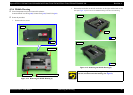
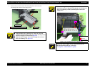
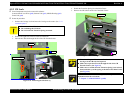
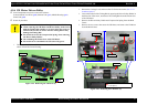
When installing the FFC Cover, insert its rib to the hole of the
CR Unit and secure it with the hook. (
See Fig.4-30.)
Printhead
Head FFC
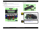
When installing the Contact Assys, secure them to the Holder
Contact Assy with two each hooks on the Contact Assys.
Figure 4-33. Assembling the Holder Contact Assy (1)
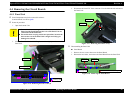
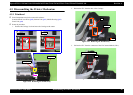
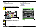
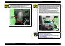
When installing the CR Contact Module, secure it with four
hooks of the Holder Contact Assy.
Figure 4-34. Assembling the Holder Contact Assy (2)
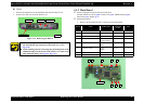
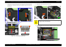
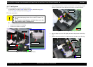
A D J U S T M E N T
R E Q U IR E D
Whenever the Printhead is removed/replaced, the required
adjustments must be carried out.
• Chapter 5 “ ADJUSTMENT” (p.100)
Front
Contact Assys
Hook
Back
CR Contact Module
Holder Contact Assy
Hook