


Epson STYLUS NX100/NX105/SX100/SX105/TX100/TX101/TX102/TX103/TX105/TX106/TX109/ME 300 Revision A
DISASSEMBLY/ASSEMBLY Disassembling the Printer Mechanism 90
Confidential
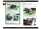
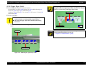
4.5.12 PF Roller
Parts/Components need to be removed in advance:
Scanner Stand/Cover Wire (p 60), Scanner Unit (p 62), Middle Housing (p 63)
Panel Unit (p 64), Main Board (p 65), EJ Roller/ EJ Frame Assy (p 73)
CR Motor/ Driven Pulley (p 75), Ink System (p 77), Main Frame(p 84)
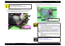
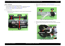
Removal procedure
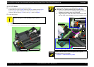
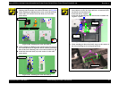
1. Remove the screw and then remove the Cover Flashing.
2. Remove the PF Roller Assy from the Lower Housing.
Figure 4-88. Removing the PF Roller Assy
C A U T I O N
Be careful not to touch the coating part of the PF Roller with bare
hands or damage it to avoid degrading the print quality.
Cover Flashing
PF Roller Assy
SCREW M3x8 P-TITE
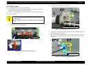
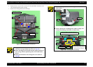
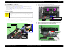
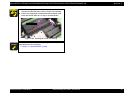
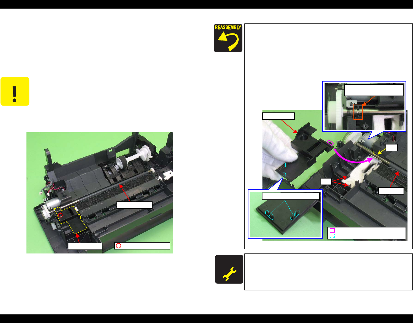
Before installing the PF Roller, align the groove of the PF Roller
Shaft with the rib of the Lower Housing. (See
Fig.4-89.)
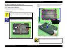
Install the Cover Flashing following the procedure below.
1. Insert the hook of the Cover Flashing through beneath the
PF Roller into the hole of the Lower Housing.
2. Align each groove on the ribs on the rear of the cover with
the ribs of the Lower Housing, and secure it with the screw.
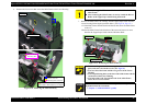
Figure 4-89. Installing the Cover Flashing
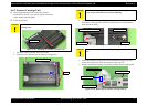
A D J U S T M E N T
R E Q U IR E D
Whenever the PF Roller is removed/replaced, the required
adjustments must be carried out.
• Chapter 5 “ ADJUSTMENT” (p.100)
Cover Flashing
PF Roller
Hole
Ribs on the rear of the Cover
Hook
Ribs on the rear of the Cover
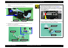
Rib
Groove of the PF Roller Shaft
and rib of the Lower Housing