


Epson STYLUS NX100/NX105/SX100/SX105/TX100/TX101/TX102/TX103/TX105/TX106/TX109/ME 300 Revision A
DISASSEMBLY/ASSEMBLY Removing the Circuit Boards 66
Confidential
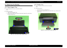
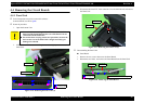
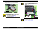
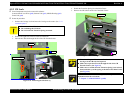
2. Remove the four screws that secure the Main Board.
3. Remove the Main Board and the Shield Plate with the PE Sensor Lever to the
ASF side as shown below.
Figure 4-21. Removing the Main Board (2)
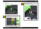
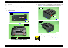
4.4.3 Power Supply Unit
Parts/Components need to be removed in advance:
Scanner Stand/Cover Wire (p 60), Scanner Unit (p 62), Middle Housing (p 63)
Panel Unit (p 64)
Removal procedure
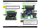
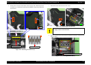
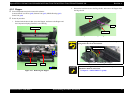
1. Disconnect the connector of the Power Supply Unit Cable (J3) from the Main
Unit and release the Power Supply Unit cable from the ribs of the Lower
Housing.
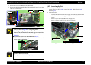
2. Remove the screw that secures the Power Supply Unit.
3. Remove the Power Supply Unit from the Lower Housing.
Figure 4-23. Removing the Power Supply Unit
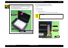
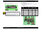
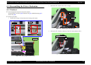
When installing the Main Board, keep the PE Sensor Lever
away (as shown in
Fig.4-21) to avoid getting broken.
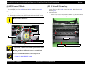
Before tightening the screws, make sure to insert the Main
Board to the rib of the Main Frame, and align the threaded hole
of the Main Frame with the hole of the Main Board. (See
Fig.4-21.)
Tighten the screws in the order indicated in Fig.4-21.
For the Shield Plate, hook its upper part to the Main Frame and
secure them as shown below.
Figure 4-22. Installing the Main board
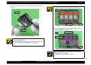
A D J U S T M E N T
R E Q U IR E D
Whenever the Main Board Unit is removed/replaced, the required
adjustments must be carried out.
• Chapter 5 “ ADJUSTMENT” (p.100)
PE Sensor Lever
Rib
PE Sensor
Shield Plate Main board
SCREW SEMS M2.6x3.5 PAN HEAD+ (7.5±0.5kgfcm)
Main Frame
Shield Plate
Power Supply Unit
Power Supply Unit cable
J3
Main board
Lower housing
SCREW M3x8 P-TITE (5±0.5kgfcm) Rib