


MCF52211 ColdFire® Integrated Microcontroller Reference Manual, Rev. 2
Freescale Semiconductor 9-1
Chapter 9
Chip Configuration Module (CCM)
9.1 Introduction
This chapter describes the various operating configurations of the device. It also provides a description of
signals used by the CCM and a programming model.
9.1.1 Features
The chip configuration for the MCF52211 is determined by the chip configuration module (CCM). The
configuration options selectable at reset are:
• Operating Mode
— Serial flash programming mode (EzPort mode)
— Single-chip mode
• Clock Reference
— External oscillator
— External crystal
— On-chip 8 MHz oscillator
• Phase-locked look (PLL)
• BDM or JTAG mode
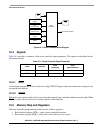
9.2 External Signal Descriptions
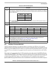
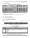
Table 9-1 provides an overview of the CCM signals.
Table 9-1. Signal Properties
Name Function Reset State
1
1
The use of external pull-up/down resistors is highly recommended.
RCON
Reset configuration select Internal weak pull-up device
CLKMOD[1:0] Clock mode select
2
2
Refer to Chapter 6, “Clock Module” for more information.
—
JTAG_EN JTAG or BDM mode selection Internal weak pull-down device
TEST Test mode selection Internal weak pull-down device