


ColdFire Core
MCF52211 ColdFire® Integrated Microcontroller Reference Manual, Rev. 2
Freescale Semiconductor 3-7
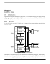
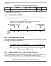
not implemented by ColdFire processors. They are assumed to be zero, forcing the table to be aligned on
a 1 MByte boundary.
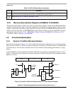
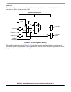
Figure 3-7. Vector Base Register (VBR)
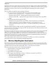
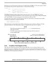
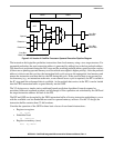
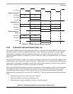
3.2.7 Status Register (SR)
The SR stores the processor status and includes the CCR, the interrupt priority mask, and other control
bits. In supervisor mode, software can access the entire SR. In user mode, only the lower 8 bits (CCR) are
accessible. The control bits indicate the following states for the processor: trace mode (T bit), supervisor
or user mode (S bit), and master or interrupt state (M bit). All defined bits in the SR have read/write access
when in supervisor mode. The lower byte of the SR (the CCR) must be loaded explicitly after reset and
before any compare (CMP), Bcc, or Scc instructions execute.
BDM: 0x801 (VBR) Access: Supervisor read/write
BDM read/write
313029282726252423222120191817161514131211109876543210
R
Base Address
0
0 0 0 0 000000000 000 0 00
W
Reset00000000000000000000000000000000
BDM: 0x80E (SR) Access: Supervisor read/write
BDM read/write
System Byte Condition Code Register (CCR)
1514131211109876543210
R
T
0
S M
0
I
000
X N ZVC
W
Reset00100111000—————
Figure 3-8. Status Register (SR)
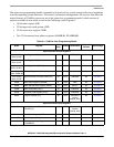
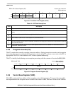
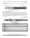
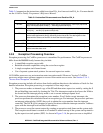
Table 3-3. SR Field Descriptions
Field Description
15
T
Trace enable. When set, the processor performs a trace exception after every instruction.
14 Reserved, must be cleared.
13
S
Supervisor/user state.
0User mode
1 Supervisor mode
12
M
Master/interrupt state. Bit is cleared by an interrupt exception and software can set it during execution of the RTE or
move to SR instructions.
11 Reserved, must be cleared.