


MCF52211 ColdFire® Integrated Microcontroller Reference Manual, Rev. 2
Freescale Semiconductor 27-1
Chapter 27
Pulse-Width Modulation (PWM) Module
27.1 Introduction
This chapter describes the configuration and operation of the pulse-width modulation (PWM) module. It
includes a block diagram, programming model, and functional description.
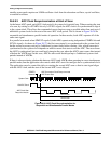
27.1.1 Overview
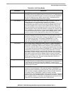
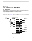
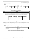
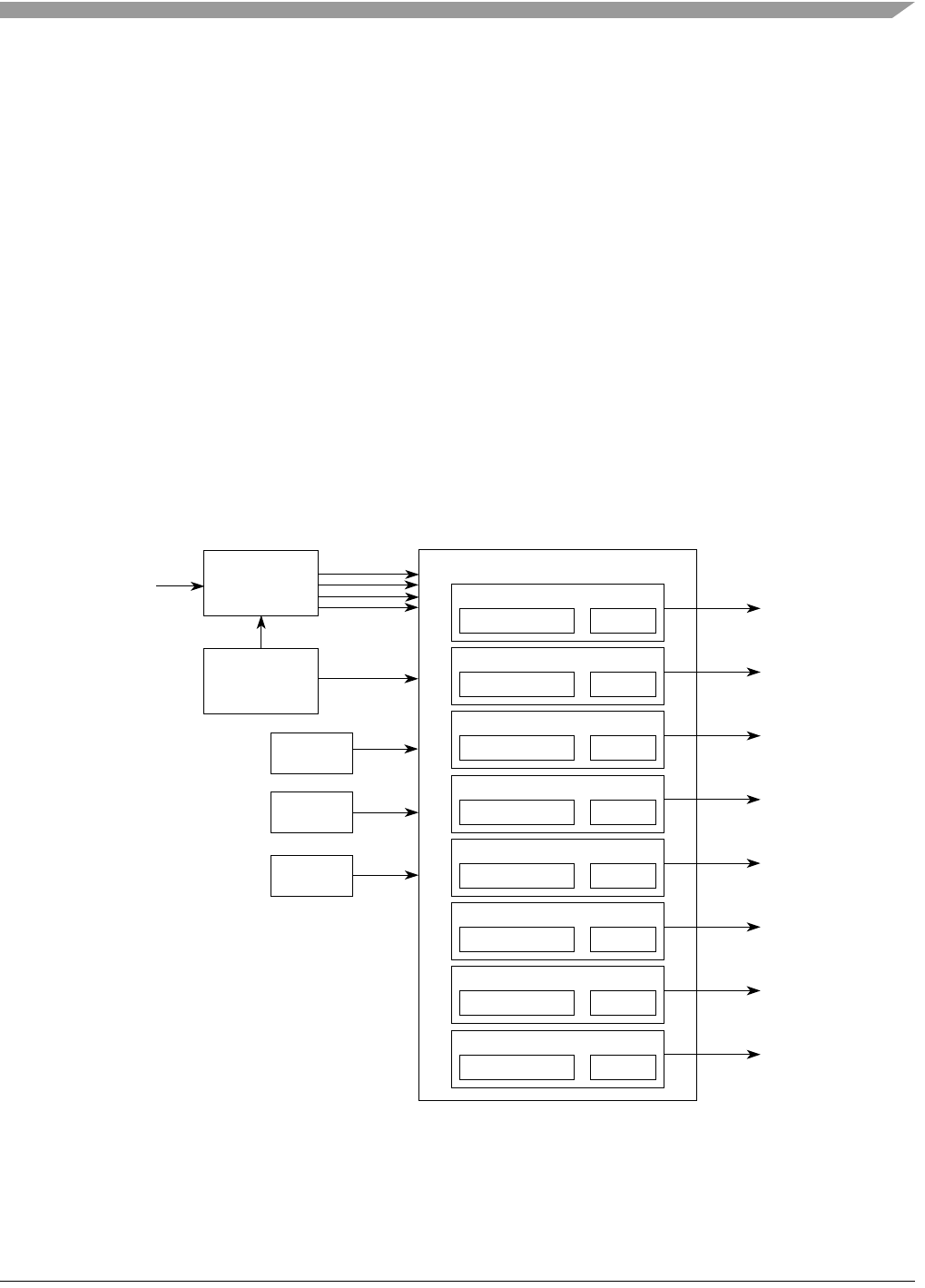
The PWM module, shown in Figure 27-1, generates a synchronous series of pulses having programmable
period and duty cycle. With a suitable low-pass filter, the PWM can be used as a digital-to-analog
converter.
Figure 27-1. PWM Block Diagram
Internal Bus
Clock (f
sys
)
Clock select
PWM Clocks
Period and Duty Counter
Channel 3
Period and Duty Counter
Channel 2
Period and Duty Counter
Channel 1
Period and Duty Counter
Channel 0
PWM Channels
Alignment
Polarity
Control
PWMOUT3
PWMOUT2
PWMOUT1
PWMOUT0
Enable
Period and Duty Counter
Channel 5
Period and Duty Counter
Channel 4
PWMOUT5
PWMOUT4
Period and Duty Counter
Channel 7
Period and Duty Counter
Channel 6
PWMOUT7
PWMOUT6