


MCF52211 ColdFire® Integrated Microcontroller Reference Manual, Rev. 2
Freescale Semiconductor 16-1
Chapter 16
Edge Port Module (EPORT)
16.1 Introduction
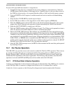
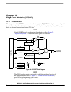
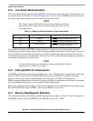
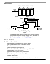
The edge port module (EPORT) has seven external interrupt pins, IRQ7–IRQ1. Each pin can be configured
individually as a level-sensitive interrupt pin, an edge-detecting interrupt pin (rising edge, falling edge, or
both), or a general-purpose input/output (I/O) pin.
NOTE
Not all EPORT signals may be output from the device. See Chapter 2,
“Signal Descriptions,” to determine which signals are available.
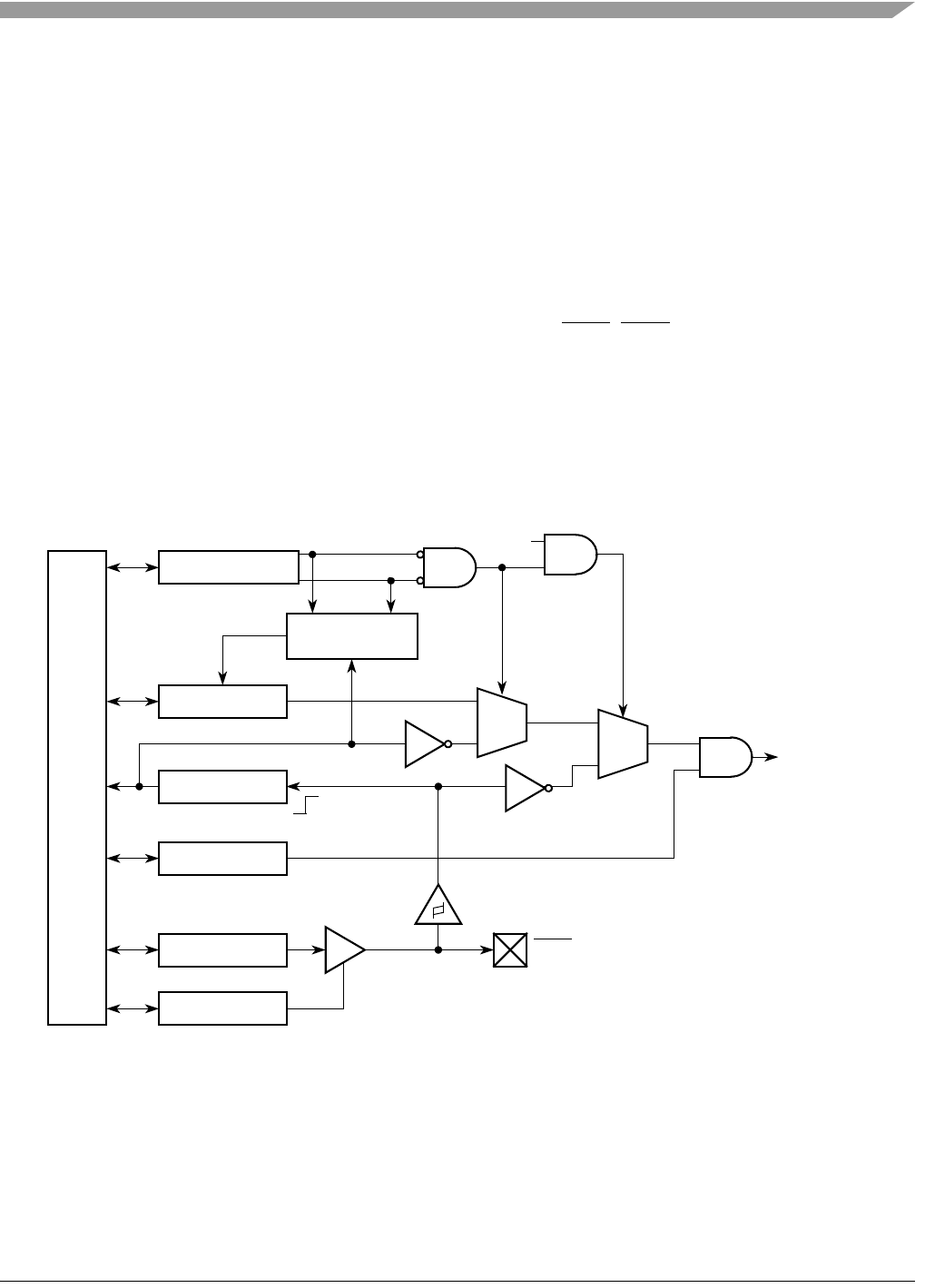
Figure 16-1. EPORT Block Diagram
NOTE
The GPIO module must be configured to enable the peripheral function of
the appropriate pins (refer to Chapter 13, “General Purpose I/O Module”)
prior to configuring the edge-port module.
Internal Bus
Synchronizer
EPDRn
EPFRn
EPPAR[2n, 2n + 1]
EPIERn
Edge Detect
D0
Stop
Logic
EPPDRn
D1
Q
D0
D1
Q
Mode
EPDDRn
To Interrupt
Controller
IRQn pin
Rising Edge
of System Clock