


ColdFire Core
MCF52211 ColdFire® Integrated Microcontroller Reference Manual, Rev. 2
Freescale Semiconductor 3-21
3.3.4.11 TRAP Instruction Exception
The TRAP #n instruction always forces an exception as part of its execution and is useful for implementing
system calls. The TRAP instruction may be used to change from user to supervisor mode.
3.3.4.12 Unsupported Instruction Exception
If execution of a valid instruction is attempted but the required hardware is not present in the processor, an
unsupported instruction exception is generated. The instruction functionality can then be emulated in the
exception handler, if desired.
All ColdFire cores record the processor hardware configuration in the D0 register immediately after the
negation of RESET. See Section 3.3.4.15, “Reset Exception,” for details.
3.3.4.13 Interrupt Exception
Interrupt exception processing includes interrupt recognition and the fetch of the appropriate vector from
the interrupt controller using an IACK cycle. See Chapter 14, “Interrupt Controller Module,” for details
on the interrupt controller.
3.3.4.14 Fault-on-Fault Halt
If a ColdFire processor encounters any type of fault during the exception processing of another fault, the
processor immediately halts execution with the catastrophic fault-on-fault condition. A reset is required to
force the processor to exit this halted state.
3.3.4.15 Reset Exception
Asserting the reset input signal (RESET) to the processor causes a reset exception. The reset exception has
the highest priority of any exception; it provides for system initialization and recovery from catastrophic
failure. Reset also aborts any processing in progress when the reset input is recognized. Processing cannot
be recovered.
The reset exception places the processor in the supervisor mode by setting the SR[S] bit and disables
tracing by clearing the SR[T] bit. This exception also clears the SR[M] bit and sets the processor’s SR[I]
bit to the highest level (level 7, 0b111). Next, the VBR is initialized to zero (0x0000_0000). The control
registers specifying the operation of any memories (e.g., cache and/or RAM modules) connected directly
to the processor are disabled.
NOTE
Other implementation-specific registers are also affected. Refer to each
module in this reference manual for details on these registers.
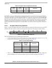
After the processor is granted the bus, it performs two longword read-bus cycles. The first longword at
address 0x0000_0000 is loaded into the supervisor stack pointer and the second longword at address
0x0000_0004 is loaded into the program counter. After the initial instruction is fetched from memory,
program execution begins at the address in the PC. If an access error or address error occurs before the first
instruction is executed, the processor enters the fault-on-fault state.