


UART Modules
MCF52211 ColdFire® Integrated Microcontroller Reference Manual, Rev. 2
Freescale Semiconductor 24-17
24.4.1.1 Programmable Divider
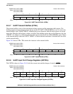
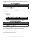
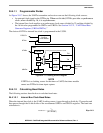
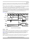
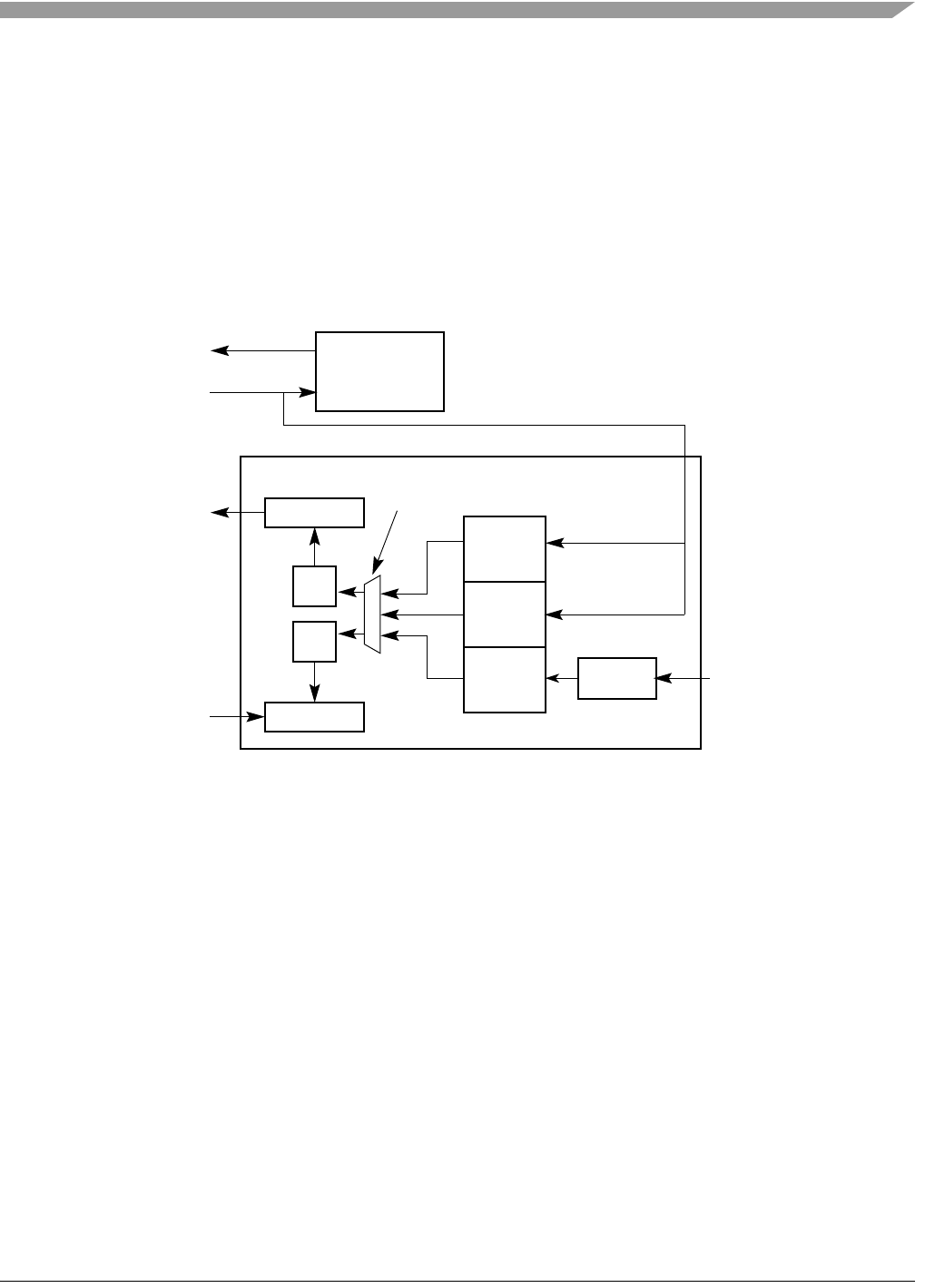
As Figure 24-17 shows, the UARTn transmitter and receiver can use the following clock sources:
• An external clock signal on the DTINn pin. When not divided, DTINn provides a synchronous
clock; when divided by 16, it is asynchronous.
• The internal bus clock supplies an asynchronous clock source divided by 32 and then divided by
the 16-bit value programmed in UBG1n and UBG2n. See Section 24.3.11, “UART Baud Rate
Generator Registers (UBG1n/UBG2n).”
The choice of DTIN or internal bus clock is programmed in the UCSR.
Figure 24-17. Clocking Source Diagram
NOTE
If DTINn is a clocking source for the timer or UART, that timer module
cannot use DTINn for timer input capture.
24.4.1.2 Calculating Baud Rates
The following sections describe how to calculate baud rates.
24.4.1.2.1 Internal Bus Clock Baud Rates
When the internal bus clock is the UART clocking source, it goes through a divide-by-32 prescaler and
then passes through the 16-bit divider of the concatenated UBG1n and UBG2n registers. The baud-rate
calculation is:
Eqn. 24-1
UART
On-Chip
TIN
÷ 1
÷ 16
16-bit
Divider
÷ 32
TIN
Clocking sources programmed in UCSR
Timer Module
Internal
Tx
Rx
Rx Buffer
Tx Buffer
f
sys
Bus Clock
URXDn
UTXDn
DTINn
DTOUTn
Baudrate
f
sys
32 x Divider[]
------------------------------------=