


Pulse-Width Modulation (PWM) Module
MCF52211 ColdFire® Integrated Microcontroller Reference Manual, Rev. 2
27-6 Freescale Semiconductor
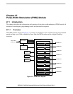
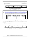
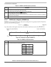
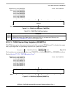
27.2.5 PWM Center Align Enable Register (PWMCAE)
The PWMCAE register contains eight control bits for the selection of center-aligned outputs or
left-aligned outputs for each PWM channel. Write these bits only when the corresponding channel is
disabled. See Section 27.3.2.5, “Left-Aligned Outputs” and Section 27.3.2.6, “Center-Aligned Outputs”
for a more detailed description of the PWM output modes.
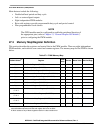
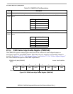
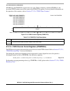
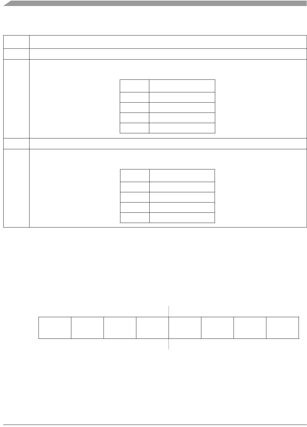
Table 27-5. PWMPRCLK Field Descriptions
Field Description
7 Reserved, should be cleared.
6–4
PCKB
Clock B prescaler select. These three bits control the rate of Clock B which can be used for PWM channels2, 3, 6
and 7.
3 Reserved, should be cleared.
2–0
PCKA
Clock A prescaler select. These three bits control the rate of Clock A which can be used for PWM channels0, 1, 4
and 5.
IPSBAR
Offset:
0x1B_0004 (PWMCAE) Access: User Read/Write
76543210
R
CAE7 CAE6 CAE5 CAE4 CAE3 CAE2 CAE1 CAE0
W
Reset:00000000
Figure 27-6. PWM Center Align Enable Register (PWMCAE)
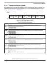
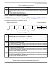
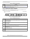
PCKB Clock B Rate
000 Internal bus clock ÷ 2
0
001 Internal bus clock ÷ 2
1
... ...
111 Internal bus clock ÷ 2
7
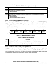
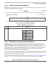
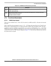
PCKA Clock A Rate
000 Internal bus clock ÷ 2
0
001 Internal bus clock ÷ 2
1
... ...
111 Internal bus clock ÷ 2
7