


Debug Module
MCF52211 ColdFire® Integrated Microcontroller Reference Manual, Rev. 2
28-22 Freescale Semiconductor
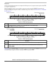
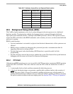
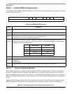
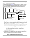
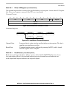
28.5.2.2 Transmit Packet Format
The basic transmit packet consists of 16 data bits and 1 reserved bit.
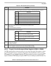
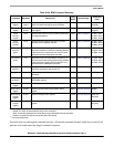
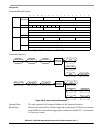
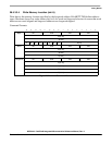
28.5.3 BDM Command Set
Table 28-20 summarizes the BDM command set. Subsequent paragraphs contain detailed descriptions of
each command. Issuing a BDM command when the processor is accessing debug module registers using
the WDEBUG instruction causes undefined behavior. See Table 28-22 for register address encodings.
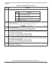
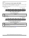
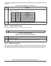
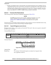
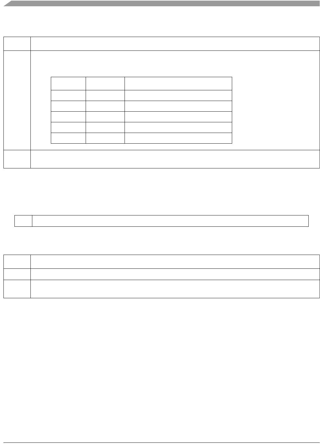
Table 28-18. Receive BDM Packet Field Description
Field Description
16
S
Status. Indicates the status of CPU-generated messages listed below. The not-ready response can be ignored
unless a memory-referencing cycle is in progress. Otherwise, the debug module can accept a new serial transfer
after 32 processor clock periods.
15–0
Data
Data. Contains the message to be sent from the debug module to the development system. The response message
is always a single word, with the data field encoded as shown above.
16 15 14 13 12 11 10 9 8 7 6 5 4 3 2 1 0
—Data
Figure 28-15. Transmit BDM Packet
Table 28-19. Transmit BDM Packet Field Description
Field Description
16 Reserved, must be cleared.
15–0
Data
Data bits 15–0. Contains the data to be sent from the development system to the debug module.
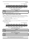
S Data Message
0 xxxx Valid data transfer
0 FFFF Status OK
1 0000 Not ready with response; come again
1 0001 Error–Terminated bus cycle; data invalid
1 FFFF Illegal Command