


General Purpose Timer Module (GPT)
MCF52211 ColdFire® Integrated Microcontroller Reference Manual, Rev. 2
Freescale Semiconductor 21-3
21.4 Low-Power Mode Operation
This subsection describes the operation of the general purpose time module in low-power modes and
halted mode of operation. Low-power modes are described in Chapter 8, “Power Management.”
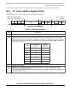
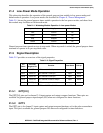
Table 21-1 shows the general purpose timer module operation in the low-power modes, and shows how
this module may facilitate exit from each mode.
Table 21-1. Watchdog Module Operation in Low-power Modes
General purpose timer operation stops in stop mode. When stop mode is exited, the general purpose timer
continues to operate in its pre-stop mode state.
21.5 Signal Description
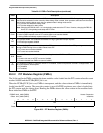
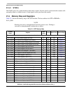
Table 21-2 provides an overview of the signal properties.
21.5.1 GPT[2:0]
The GPT[2:0] pins are for channel 2–0 input capture and output compare functions. These pins are
available for general-purpose input/output (I/O) when not configured for timer functions.
21.5.2 GPT3
The GPT3 pin is for channel 3 input capture and output compare functions or for the pulse accumulator
input. This pin is available for general-purpose I/O when not configured for timer functions.
Low-power Mode Watchdog Operation Mode Exit
Wait Normal No
Doze Normal No
Stop Stopped No
Halted Normal No
Table 21-2. Signal Properties
Pin
Name
GPTPORT
Register Bit
Function Reset State Pull-up
GPT0 PORTTn0 GPT channel 0 IC/OC pin Input Active
GPT1 PORTTn1 GPT channel 1 IC/OC pin Input Active
GPT2 PORTTn2 GPT channel 2 IC/OC pin Input Active
GPT3 PORTTn3 GPT channel 3 IC/OC or PA pin Input Active
SYNCn PORTE[3:0]
1
1
SYNCA is available on PORTE3 or PORTE1; SYNCB is available on PORTE2 or PORTE0.
GPT counter synchronization Input Active