


MCF52211 ColdFire® Integrated Microcontroller Reference Manual, Rev. 2
Freescale Semiconductor 23-1
Chapter 23
Queued Serial Peripheral Interface (QSPI)
23.1 Introduction
This chapter describes the queued serial peripheral interface (QSPI) module. After the feature set overview
is a description of operation including details of the QSPI’s internal RAM organization. The chapter
concludes with the programming model and a timing diagram.
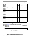
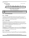
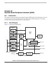
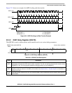
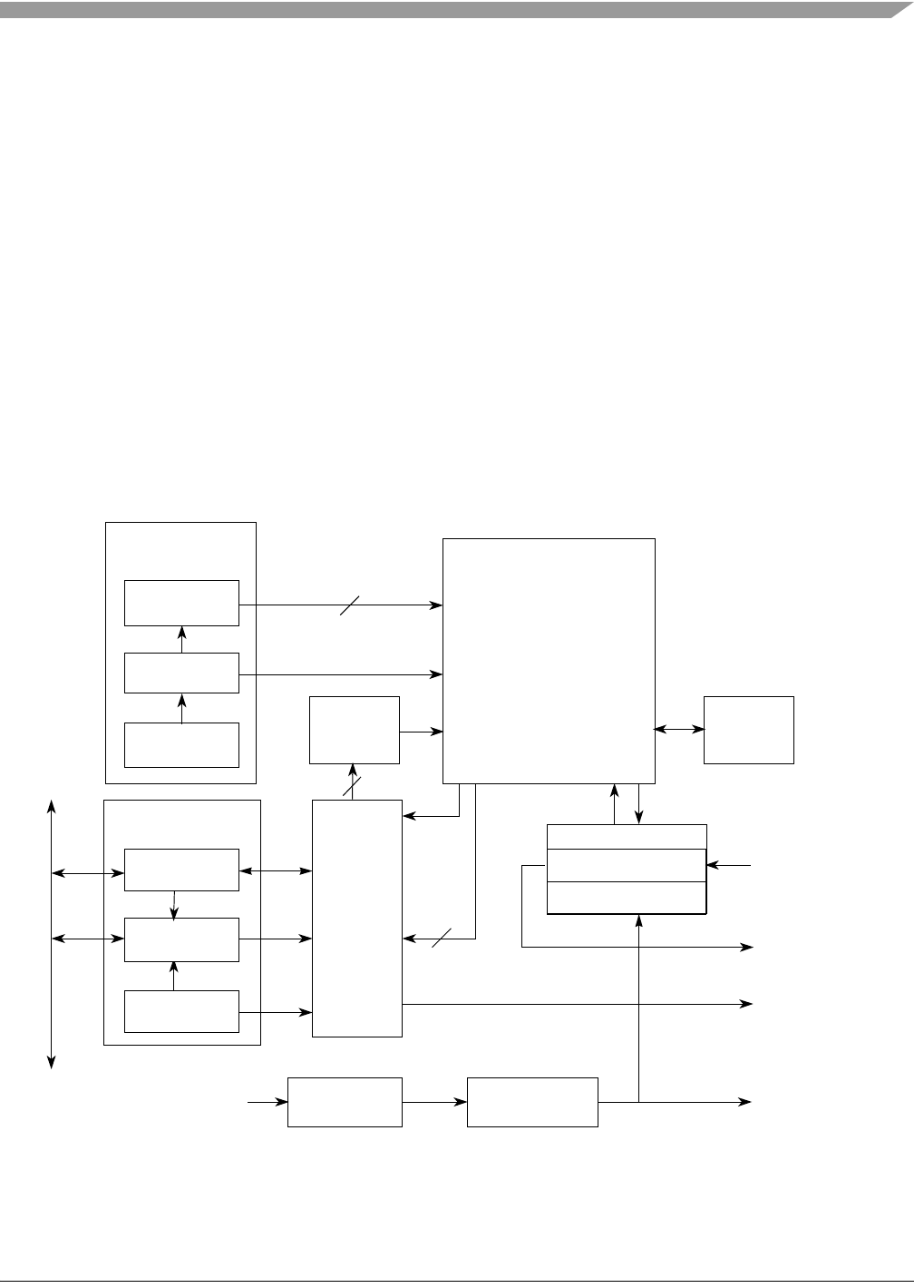
23.1.1 Block Diagram
Figure 23-1 illustrates the QSPI module.
Figure 23-1. QSPI Block Diagram
Queue Control
Block
Queue
Pointer
4
Done
Comparator
End Queue
Pointer
Status
Regs
Delay
Counter
Control Logic
Control
Regs
80-byte
QSPI
RAM
Chip
Selects
Command
Divide by 2
Baud Rate
Generator
msb lsb
Logic
Array
QSPI_CLK
QSPI_DIN
8
/16 Bit Shift Reg
.
Rx/Tx Data Reg.
QSPI_DOUT
4
4
Internal Bus
QSPI
Address
Register
QSPI
Data
Register
Internal Bus
Clock (f
sys
)
QSPI_CS[3:0]