


Interrupt Controller Module
MCF52211 ColdFire® Integrated Microcontroller Reference Manual, Rev. 2
Freescale Semiconductor 14-3
The level and priority is fully programmable for all sources except interrupt sources 1–7. Interrupt source
1–7 (from the Edge Port module) are fixed at the corresponding level’s midpoint priority. Thus, a
maximum of 8 fully-programmable interrupt sources are mapped into a single interrupt level. The fixed
interrupt source is hardwired to the given level and represents the mid-point of the priority within the level.
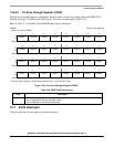
For the fully-programmable interrupt sources, the 3-bit level and the 3-bit priority within the level are
defined in the 8-bit interrupt control register (ICRnx).
The operation of the interrupt controller can be broadly partitioned into three activities:
• Recognition
• Prioritization
• Vector determination during IACK
14.1.1.1 Interrupt Recognition
The interrupt controller continuously examines the request sources and the interrupt mask register to
determine if there are active requests. This is the recognition phase.
14.1.1.2 Interrupt Prioritization
As an active request is detected, it is translated into the programmed interrupt level, and the resulting 7-bit
decoded priority level (IRQ[7:1]) is driven out of the interrupt controller.
14.1.1.3 Interrupt Vector Determination
After the core has sampled for pending interrupts and begun interrupt exception processing, it generates
an interrupt acknowledge (IACK) cycle. The IACK transfer is treated as a memory-mapped byte read by
the processor and routed to the appropriate interrupt controller. Next, the interrupt controller extracts the
level being acknowledged from address bits 4:2, determines the highest priority interrupt request active
for that level, and returns the 8-bit interrupt vector for that request to complete the cycle. The 8-bit interrupt
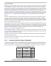
vector is formed using the following algorithm:
Vector number = 64 + Interrupt source number
Recall that vector numbers 0–63 are reserved for the ColdFire processor and its internal exceptions. Thus,
the mapping of bit positions to vector numbers is as follows:
if interrupt source 1 is active and acknowledged, then Vector number = 65
if interrupt source 2 is active and acknowledged, then Vector number = 66
...
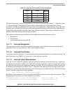
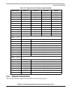
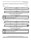
011 3 8–63
010 2 8–63
001 1 8–63
000 0 (Lowest) 8–63
Table 14-1. Interrupt Priority Within a Level (continued)
ICR[2:0] Priority
Interrupt
Sources