


Calibration
7/99 9782 Series Conductivity/Resistivity Analyzer/Controller - Operator’s Manual 8-9
Next, perform the calibration. Once calibration has been completed, go back to I/O setup and set
the solution temperature compensation type to the TDS choice, for example “NaCl (TDS)”.
At this point you are ready to enter the TDS conversion factor as described in Table 8-5.
Procedure
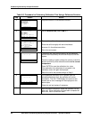
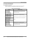
To enter the TDS conversion factor follow the instructions in in Table 8-5.
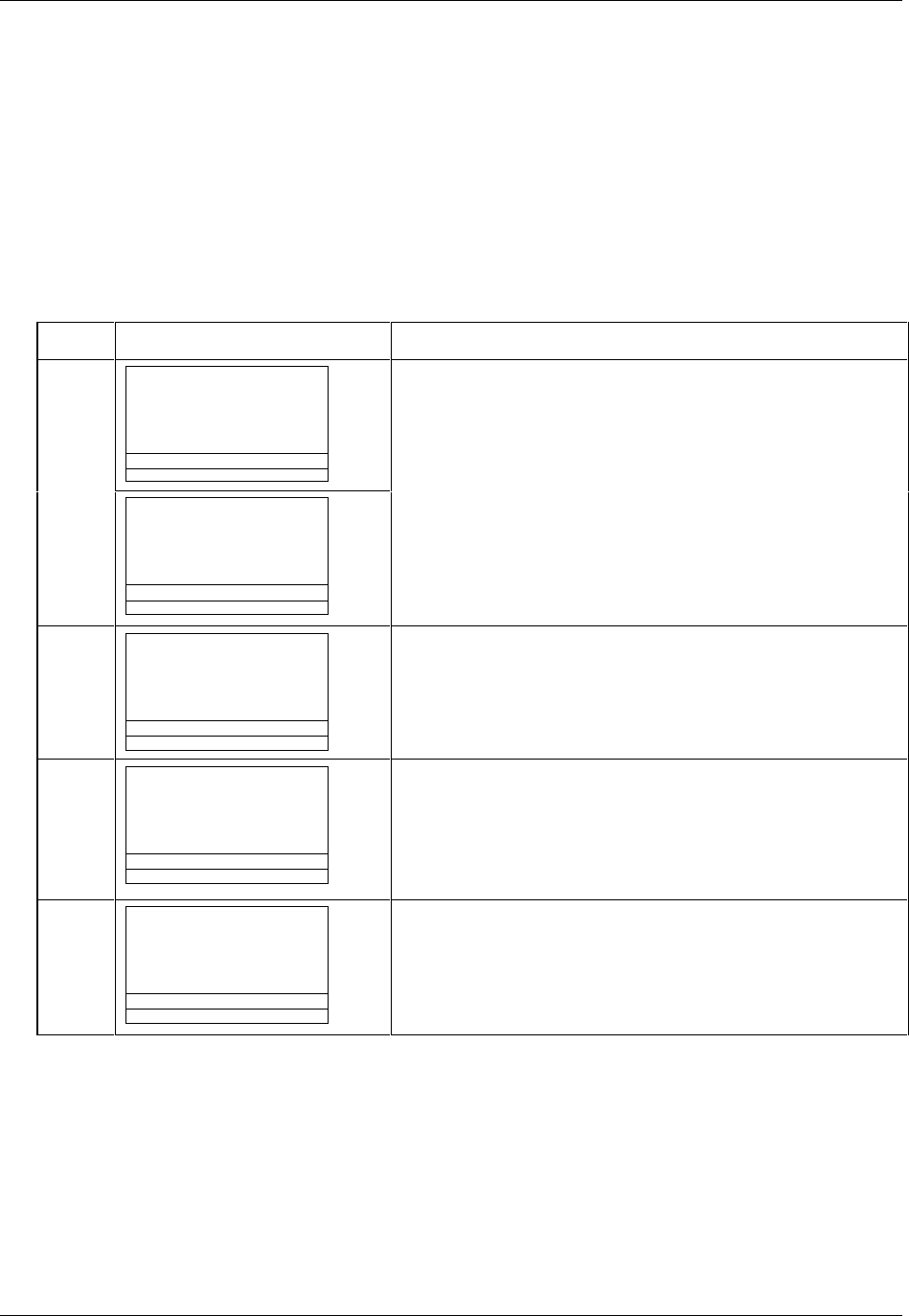
Table 8-5 Procedure for Entering TDS Conversion Factor
Step Screen Action
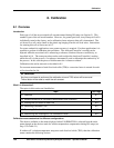
1
MENU
CONFIGURATION
CALIBRATION
MAINTENANCE
I/O SETUP
DIAGNOSTICS
| |
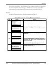
Go to CALIBRATION | TDS CVSN FACTOR C1.
CALIBRATION
CELL CAL FACTOR
TDS CVSN FACTOR C1
TDS CVSN FACTOR C2
REMOVE CAL TRIM C1
REMOVE CAL TRIM C2
DIAGNOSTICS
| |
If you plan to calibrate, do it before entering the
theoretically derived TDS conversion factor (see previous
page).
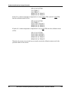
2
TDS CONVRSN FACTOR
C1 0.5
DIAGNOSTICS
| <-- | -->
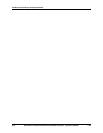
Enter the appropriate TDS conversion factor for the
selected cell.
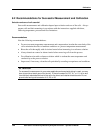
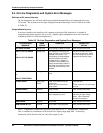
3
TDS CONVRSN FACTOR
ACCEPTED AND SAVED
DIAGNOSTICS
| |
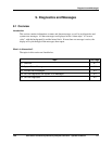
If the factor entered is within the permitted range for the
cell constant (see Table 5-10), the Analyzer/Controller will
use the entered value.
If the value is out-of-range, the Analyzer/Controller will
force the value to the appropriate range limit.
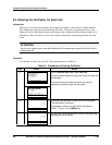
4
CALIBRATION
CELL CAL FACTOR
TDS CVSN FACTOR C1
TDS CVSN FACTOR C2
REMOVE CAL TRIM C1
REMOVE CAL TRIM C2
DIAGNOSTICS
| |
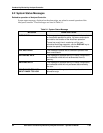
Once an acceptable factor has been entered for Cell 1,
repeat the process for Cell 2.