


I/O Setup and System Configuration
7/99 9782 Series Conductivity/Resistivity Analyzer/Controller - Operator’s Manual 5-7
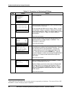
Step Screen Action
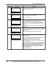
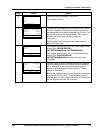
6
DISCRETE CONTROL
SELECT YES
DIAGNOSTICS
| PREV | NEXT
If any relays are still available, the screen will display a
query about discrete control.
7
DISCRETE CONTROL TYPE
RELAY 3 N/A
RELAY 4 DAT
DIAGNOSTICS
| PREV | NEXT
If discrete control will be used, select the relay(s) to be
used and the type of control for each.
Go to the next screen.
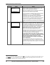
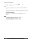
8
RELAY ASSIGNMENTS
RLY1 RLY2 RLY3 RLY4
ACLN RNGS AA DAT
DIAGNOSTICS
| PREV | NEXT
If any relays are still available, then indicate which feature
will be associated with each available relay. In our
example, only Relay 3 can be assigned using this screen.
Relays 1, 2 and 4 have already been dedicated to other
functions.
However, by selecting AA, all alarms can be directed to a
single relay.
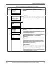
9
RELAY ACTIVATION
STATE ON ALARM
SELECT DE-ENERGIZE
DIAGNOSTICS
| PREV | NEXT
The display will indicate whether relay activation in case of
alarm (or control output “ON” state) is currently ENERGIZE
or DE-ENERGIZE.
Use this display to specify the desired relay action.
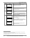
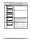
10
MEASUREMENT TYPE
SELECT COND/TDS
DIAGNOSTICS
| PREV | NEXT
Specify the type of measurement to be performed by the
Analyzer/Controller.
If you specify any measurement type other than the default
(conductivity/total dissolved solids), the unit will
immediately perform a cold reset, returning all
configuration and calibration trim (or TDS factor) values to
the factory defaults.
A cold reset will also return some I/O setup values to
factory settings. If you change the measurement type,
be sure to cycle through all the other I/O setup
screens and check that the settings are appropriate
for your application.
Go to the next screen.