


Conductivity/Resistivity Analyzer/Controller
9782 Series Conductivity/Resistivity Analyzer/Controller - Operator’s Manual 7/996-6
9
SH
G
R
G
R
W
K
W
K
NC
COM
NO
NC
COM
NO
L1 (K)
L2 /N
Relay 2
Note 1
Relay 1
Note 1
120V/240V
15A
50-60 Hz
Note 5
Power &
Relay Terminals
No. 2 Temp.
Compensator
No. 1 Temp.
Compensator
Cell 2
Electrodes
Cell 1
Electrodes
Note 4
Case (as viewed from front)
Note 3
NO
COM
NC
NO
COM
NC
8
7
6
5
4
3
2
1
Voltage & Current
Output Terminals
+
-
+10
VC
+1
mA
I(+)
I(-)
+10V 2000 min
VCom
+1V 200 min
4-20 mA 600 min
NO
COM
NC
NC
COM
NO
Relay 3
Note 6
Relay 4
Note 6
Relay Terminals
(optional)
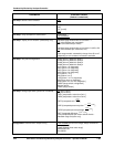
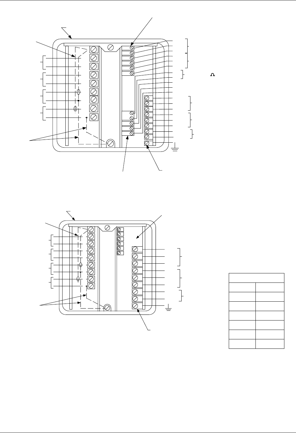
Two-Cell Cat. 9782 with Output/relays
9
8
7
6
5
4
3
2
1
SH
G
R
G
R
W
K
W
K
NC
Com
NO
NC
Com
NO
L1(K)
L2/N
Relay 2
Note 1
Relay 1
Note 1
120V/240V 15A
50-60 Hz
Note 5
Power &
Relay Terminals
No. 2 Temp.
Compensator
No. 1 Temp.
Compensator
Cell 2
Electrodes
Cell 1
Electrodes
Note 4
Case (as viewed from front)
Note 3
1
2
3
4
5
6
OUT1-
OUT1+
OUT2-
OUT2+
OUT3-
OUT3+
Output Board
Connections
(4-20 mA)
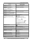
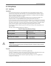
Two-Cell Cat. 9782 - MultiOptions
K- black
W- white
G- green
R- red
B- blue
N- brown
O- orange
Y- yellow
A- gray
V- violet
P- pink
S- slate
T- tan
Color Code
a/n 23177
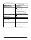
NOTES:
1. Relay 1 & 2 contacts max. ratings
(Resistive Load)
Current: 2A AC or DC
Voltage: 250 VAC, 220 VDC
Switching Power: 125VA, AC: 60 W, DC.
2. See Cell Connection Diagram or directions
for wiring restrictions.
3. Coaxial cable used with greater than 20 ft.
cell/Analyzer seperation with Standard
Range instruments only.
4. For pure water samples in plastic piping,
ground the black cell electrode lead near
the cell. Alternately, connect to the 9782
ground screw as shown dotted. DO NOT
ground 10, 25 or 50 constant cells.
5. Analyzer is factory set for 120V operation.
For 240V operation, see "Power
Connections" in this manual.
6. Relay 3 & 4 contact ratings 3A @ 120V AC/
28 VDC resistive.
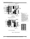
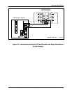
Figure 6-1 Terminal Connections