


Maintenance
7/99 9782 Series Conductivity/Resistivity Analyzer/Controller - Operator’s Manual 10-3
10.2 Output Calibration
Introduction
The 9782 is available with one or more optional analog outputs. The output signals can be
adjusted to trim the high and low output current or voltage values over a range of ±0.4% of span
to compensate for component tolerance variations.
Required equipment
Output calibration involves connecting a meter to the Analyzer/Controller’s output terminals.
The meter required for output calibration depends on the type of outputs.
• current outputs: current meter capable of resolving 0.01 mA over the range 0 to 20 mA dc
• voltage outputs: a 250 ohm ±0.05% shunt and a volt meter (capable of measuring 1 to 5 Vdc
within 1 mV)
A screwdriver to fit the terminal block screws is also required.
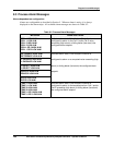
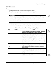
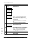
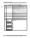
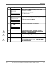
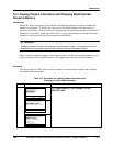
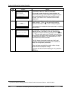
Procedure
To calibrate outputs, follow the procedure described in Table 10-1. The output terminals are
inside the case as shown in Figure 6-1.
WARNING
While the unit is powered, a potentially lethal shock hazard exists inside the case. Do not open
the case while the unit is powered. Do not access the output terminal as described below while
the unit is powered.
WARNING
A disconnect switch must be installed to break all current carrying conductors. Turn off power
before working on conductors. Failure to observe this precaution may result in serious personal
injury.