


I/O Setup and System Configuration
7/99 9782 Series Conductivity/Resistivity Analyzer/Controller - Operator’s Manual 5-13
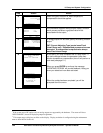
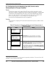
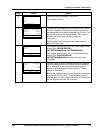
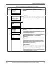
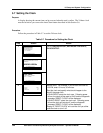
Table 5-3 Procedure for Configuring On/Off Control
Step Screen Action
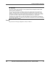
1
MENU
CONFIGURATION
CALIBRATION
MAINTENANCE
I/O SETUP
DIAGNOSTICS
| PREV | NEXT
Go to CONFIGURATION | DISCRETE CONTROL |
ON/OFF.
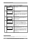
CONFIGURATION
CAT/RETRANSMISSION
ALARMS
DISCRETE CONTROL
ADVANCED FEATURES
DIAGNOSTICS
| PREV | NEXT
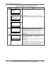
ATTENTION: Any value entered for one of these control-
related parameters will take effect as soon as it is entered.
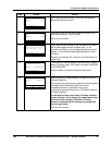
DISCRETE CONTROL
ON/OFF
PFT
DAT
DIAGNOSTICS
| |
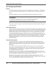
2
ON/OFF CONTROL
CYCLE PERIOD 500s
CYCLE TMR 1
CYCLE TMR 2
CYCLE TMR 3
CYCLE TMR 4
DIAGNOSTICS
| |
Use this screen to specify the length of the cycle period for
all timers.
To configure an individual timer associated with one of the
relays, select it from the menu.
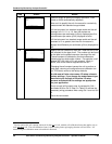
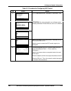
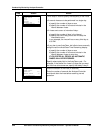
3
CYCLE TIMER 1 RLY2
INPUT C1
ACTION HIGH
SETPOINT 15000 µS
DEADBAND 250 µS
ONTIME 50%
DIAGNOSTICS
| |
The relay assigned to this On/Off control output during I/O
setup will already be filled in. (This is read-only
information.)
Specify the process value or computed value to be used
as the input.
Specify whether relay activation should occur when the
input’s value exceeds the setpoint (HIGH action) or falls
below the setpoint (LOW action).
Enter the setpoint.
If desired, specify a deadband. (Once the output is ON, it
will remain ON until the controlled variable differs from the
setpoint by at least the value of the deadband.)
Enter the percent of the cycle period that the relay should
stay on when the setpoint is reached.