


Conductivity/Resistivity Analyzer/Controller
9782 Series Conductivity/Resistivity Analyzer/Controller - Operator’s Manual 7/993-4
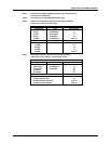
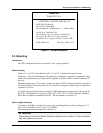
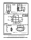
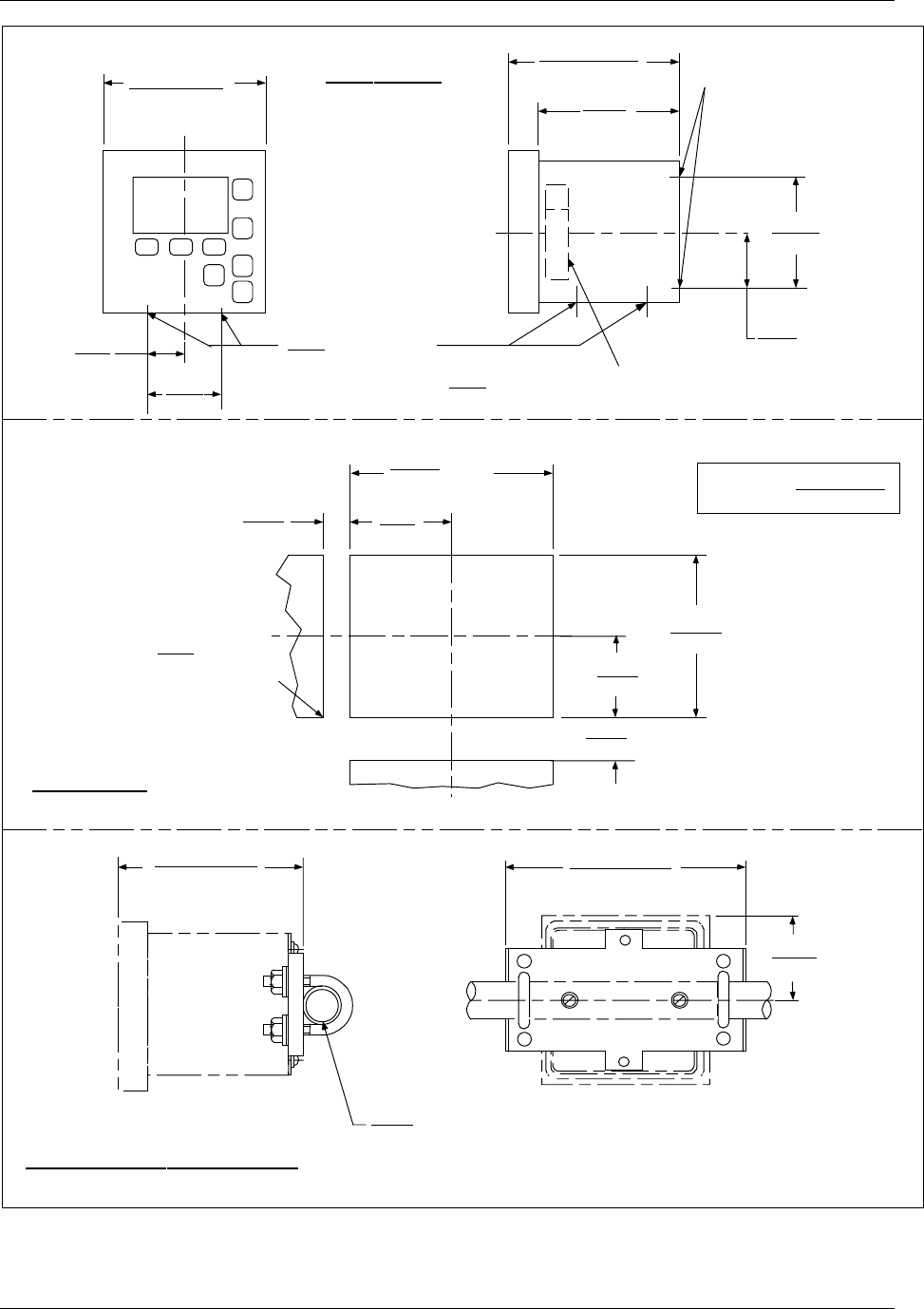
Figure 3-2-1 Mounting and Dimensions – Non-Backlit Display Option
7.68 ± .060
195.07 ± 1.52
3.06
77.80
7.43 ± .070
188.72 ± 1.78
1.00
25.40
IPS Pipe
(by customer)
Note 1: Do not exceed 80 lb-in torque
when tightening fastners.
Horizontal Rear Pipe Mounting
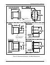
6.12 ± .030
155.57 ± 0.76
1.37
34.92
2.75
69.85
C
L
2.41
61.21
4.81
122.17
C
L
6.00
152.40
(2) ¼-20 Tapped Holes
in rear of case for
mounting bracket
Dia holes (4)
for lead wires,
accomodates conduit
by customer
.87
22.22
.50
12.70
Square
Terminal Boards
Case Outline
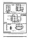
7.00 ± .040
177.80 ± 1.02
2.76
70.05
min space
between
horizontal
cutouts
.687
17.45
5.516
140.11
+.047
- 0
+1.19
- 0
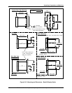
5.516
140.11
+.047
- 0
+1.19
- 0
2.76
70.05
.125
3.18 R max
permissible
.937
23.81
min space between
vertical cutouts
Panel Cutout
inches
millimeters
LEGEND: