


Input and Output Wiring
7/99 9782 Series Conductivity/Resistivity Analyzer/Controller - Operator’s Manual
6-1
6. Input and Output Wiring
6.1 Overview
Introduction
This section contains instructions for installing input and output wiring for the
Analyzer/Controller.
We recommend that you wait to install input and output wiring until after I/O setup (see
Section 5). During I/O setup the software will determine for you which relay to use for each
feature.
ATTENTION
If you plan to use a computed value such as the difference between the cell readings, it matters
which cell is “Cell 1” and which is “Cell 2”. See 6.4.3 for details.
ATTENTION
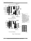
For successful measurement in pure water applications where plastic piping is used, you may
have to provide an earth ground for the cell. If the cell constant is 0.01, 0.1, or 1.0, run a wire
from the screw terminal (on the Analyzer/Controller ) to which the black wire in the cell lead is
attached to the lower card retainer bracket screw. (See Note 4 in Figure 6-1.)
Do not ground cells having cell constants of 10, 25, or 50.
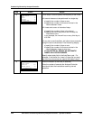
What’s in this section?
The topics in this section are listed below.
Topic See Page
6.1 Overview 6-1
6.2 General Wiring Practices for I/O Wiring 6-2
6.3 Wiring Analog Inputs and Outputs 6-4
6.4 Wiring Relays 6-7
WARNING
While the unit is powered, a potentially lethal shock hazard exists inside the case. Do not open
the case while the unit is powered. Disconnect power before installing I/O wiring. More than one
switch may be required to disconnect power.