


Conductivity/Resistivity Analyzer/Controller
9782 Series Conductivity/Resistivity Analyzer/Controller - Operator’s Manual 7/996-10
6.4.3 Wiring a Device to the Relay Indicating Output Range Status
Introduction
If the automatic output range change feature is selected during I/O setup, one relay is dedicated
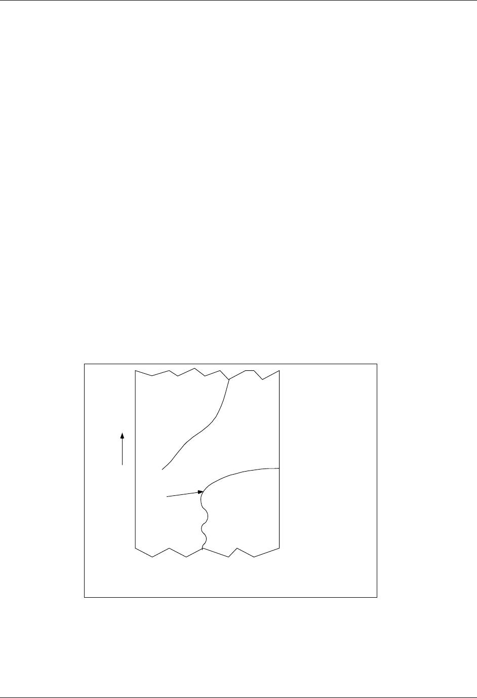
to this function. The relay can be used to control an indicator, or to switch the output to a second
channel of a multipoint recorder when the range change occurs (see Figure 6-2). Check the
current relay assignments as described in Section 5 to determine whether a relay was assigned to
this feature.
This feature closes contacts NC-COM when the output is scaled to the low range (Range 1 in
Figure 6-2) and closes contacts NO-COM when scaled to the high range (Range 2 in Figure
6-2).
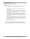
Interconnections
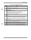
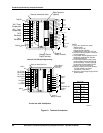
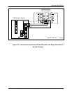
The range change capability illustrated in Figure 6-2 is accomplished with interconnections
shown in Figure 6-3. Similar range identification could be obtained using a 2-pen or event-pen
recorder.
Point 1/Terminals 1 - low range (0-1µS/cm)
Point 2/Terminals 2 - high range (0-10 µS/cm)
Resistors “R” across the recorder inputs are needed to ensure that the unused point will remain at
the low end of scale. The resistance value can be anything from 500 ohms to 1 Mohm.
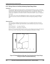
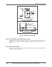
(simulated
condenser
leak)
Time
Range 1 0 .2 .4 .6 .8 1.0
Range 2 0 2 4 6 8 10
a/n 23178
Figure 6-2 Sample Multipoint Recorder Chart Illustrating Auto Output Range
Change for Steam Condensate Monitoring