


Conductivity/Resistivity Analyzer/Controller
9782 Series Conductivity/Resistivity Analyzer/Controller - Operator’s Manual 7/995-4
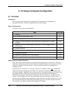
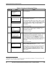
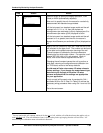
5.3 Performing I/O Setup
Purpose
Before you can configure your Analyzer/Controller to implement your alarm and control strategy
you must perform I/O setup. In I/O setup you choose the features to be used, based on the
hardware capability of the 9782 model being configured. Using your selections, the software
will display the relay and analog output assignments appropriate for your application. The
choices made during I/O setup determine which prompts and menu choices are available during
configuration. For a discussion of the features available, and of the interactions affecting relay
assignments, see Section 1.
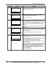
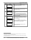
I/O setup is also used to specify relay action. The relay action used for alarm and/or control
action for all relays in the Analyzer/Controller can be specified as energized or de-energized on
alarm (or when discrete control point is ON).
In addition, I/O setup is used to specify display resolution and unit of measure (see below).
Display resolution and unit of measure
For standard range models (9782C-S0), the resolution of the display of conductivity or resistivity
can be selected. (No other displays are affected.)
• When set to LOW, the decimal point is fixed. It remains in the same place throughout the
display range.
• When set to HIGH, the decimal point will automatically be shifted one place to the left to
provide greater resolution when the displayed value falls below 10% of the high display
range, and conversely, be shifted back when the value increases above 10%.
This selection of low or high display range has no effect on the fixed or auto output range status.
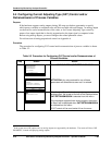
For conductivity measurement the unit of measure can also be specified for standard range
Analyzer/Controllers. No unit of measure is displayed for wide range models. The
Analyzer/Controller automatically uses the conductivity unit of measure appropriate for the cell
constant (see Wide Display Ranges table in Sub-Section 2.1.5.)
ATTENTION
If you use I/O setup to view parameters, making no changes, a cold reset will not occur.
However, if you change any parameter other than the type of solution for which temperature
compensation should be applied, you will cause the Analyzer/Controller to perform a cold reset
(see page 5-1). This cold reset is necessary to ensure that the integrity of the unit remains intact
when critical parameters have been changed.
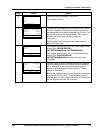
ATTENTION
AutoClean and range status indication cannot be selected for use with two cells simultaneously.
Your choices are:
• For Cell 1 only, use AutoClean (Relay 1) and/or range status indication (Relay 2).
• For both Cell 1 and Cell 2, use AutoClean (Relays 1 and 3), with no range status indication,
nor any discrete control.
• For both Cell 1 and Cell 2, use range status indication (Relays 2 and 4), with no AutoClean,
nor any discrete control.