


Diagnostics and Messages
7/99 9782 Series Conductivity/Resistivity Analyzer/Controller - Operator’s Manual 9-3
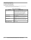
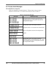
9.3 Process Alarm Messages
Alarms dependent on configuration
Alarms are configurable as described in Section 5. When an alarm is active, it is always
displayed on the alarm stripe. All available alarm messages are shown in Table 9-2.
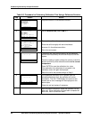
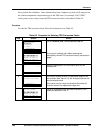
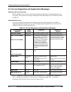
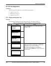
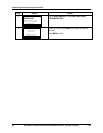
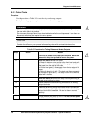
Table 9-2 Process Alarm Messages
MESSAGE WHEN DISPLAYED
CELL 1 HIGH ALM
CELL 1 LOW ALM
CELL 2 HIGH ALM
CELL 2 LOW ALM
CELL1 OR 2 HIGH ALM
CELL 1 OR 2 LOW ALM
Indicates alarm state, if the Analyzer/Controller is
configured to alarm on the Cell 1 and/or Cell 2 value
exceeding (high alarm) or falling below (low alarm) the
configured alarm setpoint.
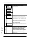
DIFFERENCE HIGH ALM
DIFFERENCE LOW ALM
Indicates alarm state, if the Analyzer/Controller is
% PASSAGE HIGH ALM
% PASSAGE LOW ALM
configured to alarm on a computed value exceeding (high
% REJECT HIGH ALM
% REJECT LOW ALM
alarm) or falling below (low alarm) the configured alarm
PPM CO2 HIGH ALM
PPM CO2 LOW ALM
setpoint.
RATIO HIGH ALM
RATIO LOW ALM
TEMP 1 HIGH ALM
TEMP 1 LOW ALM
TEMP 2 HIGH ALM
TEMP 2 HIGH ALM
TEMP 1 OR 2 HIGH ALM
TEMP 1 OR 2 LOW ALM
Indicates alarm state, if the Analyzer/Controller is
configured to alarm on the temperature from Cell 1 and/or
Cell 2 exceeding (high alarm) or falling below (low alarm)
the configured alarm setpoint.