


I/O Setup and System Configuration
7/99 9782 Series Conductivity/Resistivity Analyzer/Controller - Operator’s Manual 5-11
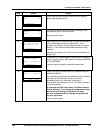
Step Screen Action
3
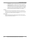
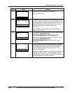
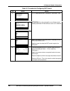
CAT CONTROL
CAT1
CAT2
CAT3
DIAGNOSTICS
| PREV | NEXT
Select an output to configure it for control.
Go to the next screen.
4
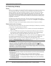
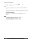
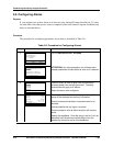
CAT CONTROL OUTPUT 1
SCALING LINFIXEDRNG
INPUT C1
SETPOINT 12000
µ
S
PB LIMIT 300
µ
S
DIAGNOSTICS
| PREV | NEXT
The input type and appropriate unit of measure will already
be filled in, based on the process variable or computed
value assigned to this analog output during I/O setup. The
scaling characteristic will also be filled in; CAT output is
always linear fixed-range. (All this is read-only
information.)
Use the setpoint and proportional band parameters to
define the output span.
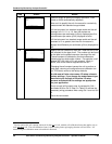
5
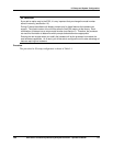
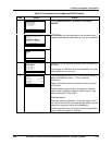
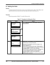
RETRANSMISSION
OUTPUT 1
OUTPUT 2
DIAGNOSTICS
|
PREV
|
NEXT
To configure retransmission on a unit with a single analog
output, go to CONFIGURATION |
CAT/RETRANSMISSION | RETRANSMISSION.
To configure retransmission on a unit with three analog
outputs go to CONFIGURATION |
CAT/RETRANSMISSION and select the output to be
configured.
6
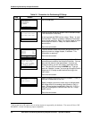
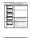
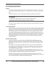
OUTPUT 1
SCALING LINFIXEDRNG
INPUT C1
0% 0.0
µ
S
100% 19.0
µ
S
DIAGNOSTICS
| PREV | NEXT
For each output to which a process variable or computed
value was assigned during I/O setup, the value assigned
will be displayed, as well as the type of scaling to be
applied, and the appropriate unit of measure. (This is
read-only information.)
Specify the range by entering the values to be represented
by outputs of 0% and 100%. If reverse-acting output is
required, enter the high range value at the 0% prompt and
the low range value at the 100% prompt.