


Conductivity/Resistivity Analyzer/Controller
9782 Series Conductivity/Resistivity Analyzer/Controller - Operator’s Manual 7/996-4
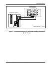
6.3 Wiring Analog Inputs and Outputs
Introduction
Every 9782 Analyzer/Controller requires input signals from the cells.
In addition, some 9782 models provide from one to three analog output signals (current and/or
voltage) that can be used to retransmit process variables, or to provide Current Adjusting Type
control (see 1.5.3).
Wiring these analog inputs and outputs is described here. Wiring relay outputs is described in
6.4.
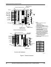
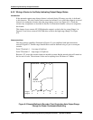
Cell identification significant to computed value
The 9782 can compute a value (choices listed below), then display the value, and, if desired, use
it as the basis for control or alarming. (Sample applications are shown in Appendix B.) Each of
these computed values is calculated based on the process variable value measured by both cells.
Therefore, it matters which cell is considered “Cell 1” and which is “Cell 2”. The
Analyzer/Controller determines the cell’s identity based upon which terminals receive the cell’s
input (see Figure 6-1). If you have set up the 9782’s software to use a computed value, be
sure to wire the cell leads correctly.
The available computed values are:
• RATIO: ratio between the values measured by the cells;
Cell
Cell
1
2
• DIFFERENCE: difference between the values measured by the cells;
Cell Cell12−
• %PASSAGE: computed percent passage:
Cell
Cell
x
1
2
100
• %REJECTION: computed percent rejection:
()x1
1
2
100−
Cell
Cell
• PPMCO2: computed parts per million carbon dioxide (9782C-S0 only)
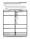
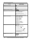
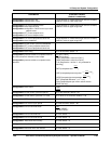
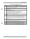
Procedure
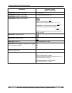
Follow the procedure in Table 6-2 to install analog I/O wiring.
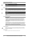
WARNING
While the unit is powered, a potentially lethal shock hazard exists inside the case. Do not open
the case while the unit is powered. Disconnect power before installing I/O wiring. More than one
switch may be required to disconnect power.