


Conductivity/Resistivity Analyzer/Controller
9782 Series Conductivity/Resistivity Analyzer/Controller - Operator’s Manual 7/999-8
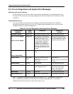
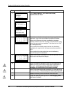
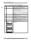
Step Screen Action
7
MENU
CONFIGURATION
CALIBRATION
MAINTENANCE
I/O SETUP
DIAGNOSTICS
| PREV | NEXT
Go to MAINTENANCE | OFF-LINE FUNCTIONS |
OUTPUT/RELAY TEST.
MAINTENANCE
OFFLINE FUNCTIONS
INSTRUMENT SETUP
LEAD RESISTANCE COMP
DIAGNOSTICS
| PREV | NEXT
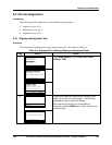
OFF-LINE FUNCTIONS
DISPLAY TEST
KEYBOARD TEST
OUTPUT/RELAY TEST
OUTPUT CALIBRATON
DIAGNOSTICS
| PREV | NEXT
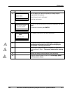
OUTPUT TEST
01 02 03 R1R2R3R4
0 0 0 A A A A
25 0 0 A A A A
50 25 0 A A A A
75 50 25 A A N A
DIAGNOSTICS
| | NEXT
Select the combination of output values to be supplied to the
terminals, or go to the next window for additional choices.
When one of the rows of output combinations has been
selected, observe the meter readings to check that the analog
output values match those selected. Also listen for the “click”
of an energized relay.
If the results of the analog output test are not satisfactory,
recalibrate the output’s zero and span using the procedure in
10.2.
If the results of the relay output test are not satisfactory,
consult Honeywell for assistance.
9
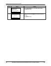
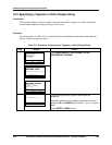
OUTPUT TEST
01 02 03 R1R2R3R4
100 75 50 A A A N
0 100 75 A N A A
0 0 100 A A N A
0 0 0 A N N N
DIAGNOSTICS
| PREV |
Select one of these combinations, or use the specified function
key to return to the previous display.
10
If only one meter is available, so that only one output can be
tested at a time, then for each analog output repeat Steps 1
through 9, including powering down the unit before
changing the connections to the output terminals.
11
When output testing has been completed, re-install field wiring
removed in Step 4. Disconnect power before opening case.
12
Replace the safety cover and secure it with the screw.
13
Close the case and power up the unit. Do not apply power
until case is closed.