


Maintenance
7/99 9782 Series Conductivity/Resistivity Analyzer/Controller - Operator’s Manual 10-13
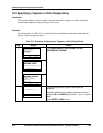
Procedure
To use the 9782’s automatic compensation for lead resistance, enter the necessary values using
the procedure in Table 10-7.
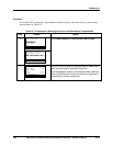
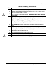
Table 10-7 Procedure for Entering Values for Lead Resistance Compensation
Step Screen Action
1
MENU
CONFIGURATION
CALIBRATION
MAINTENANCE
I/O SETUP
DIAGNOSTICS
| PREV | NEXT
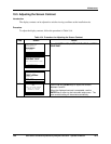
Go to MAINTENANCE | LEAD RESISTANCE COMP.
MAINTENANCE
OFFLINE FUNCTIONS
INSTRUMENT SETUP
LEAD RESISTANCE COMP
DIAGNOSTICS
| PREV | NEXT
2
LEAD RESISTANCE COMP
WIRE GAUGE 12AWG
WIRE LENGTH
CELL1 100FT
CELL2 150FT
DIAGNOSTICS
| PREV | NEXT
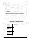
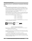
Use this screen to specify the gauge used for leads to both
cells, and the length of one lead to each cell.
If mixed gauges are used, or the length exceeds 1999 feet,
refer to the Introduction of this sub-section for guidance in
computing the values to enter here.