


UMC800 Overview
UMC800 Description
Release F UMC800 Controller Installation and User Guide 3
4/01
UMC800 Overview
UMC800 Description
The Universal Multiloop Controller (UMC800) is a modular controller designed to address the analog and
digital control requirements of small unit processes. With up to 16 analog control loops, four setpoint
programmers, and an extensive assortment of analog and digital control algorithms, the UMC800 is an
ideal control solution for furnaces, environmental chambers, ovens, reactors, cookers, freeze dryers,
extruders, and other processes with similar control requirements.
Accommodating up to 64 universal analog inputs, 16 analog outputs, and 96 digital inputs/outputs, the
UMC800 provides the appropriate balance of input and output hardware for these smaller unit processes.
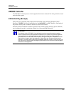
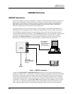
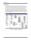
The UMC800 uses separate hardware for control functions and operator interface functions to provide
greater installation flexibility. See Figure 1. The controller incorporates card slots capable of supporting up
to 16 input and output modules that can be mixed to satisfy the hardware requirements of a specific
application. The operator interface uses a color graphic LCD display to provide a variety of display
presentations for viewing control loops, setpoint programs, and other analog and digital status.
_
100 - 2 30 V ~
50 / 60 Hz
100 VA MAX.
F 3,15 A T
L1
L2 /
N
UMC800
Controller
POWER
LoBAT
FO R CE
RUN
DISPLAY
BA T
CONFIGURATI ON
OFFLI NE
RUN
PROG RAM
COMM B COMM A
Replace ba tte r y wi th Tadi r an TL5101/ S
only . Use of a nother battery may
present a r i s k of f ire or ex pl os i o n.
See users g ui de for instr uct ion s.
PC or Laptop with
Control Builder
Configuration Software,
On-Line Help and
User Utility Software
Operator Interface
To Field
Devices
RS 485 Serial
Communications with
Modbus RTU Protocol
(Optional)
Figure 1 UMC800 components
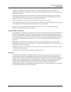
A separate “Control Builder” configuration software program is used for system configuration that
operates on a Windows 95- or NT-based PC. The software program uses graphic symbols and line drawing
connections to create custom control strategies. Menus are provided in the software to allow selection of
screens for the operator interface and to customize screen access methods and operator keys. Completed
configurations are loaded into the control system using a dedicated communications port in the controller,
or optionally, via floppy disk. A separate User Utility software program (also running on a PC) is used to
create, edit, save, open and download individual recipe, profile and data storage files. Calibration of the
analog input and output modules can be performed through this utility program. A modem connection