


Mounting and Wiring
Remote Access
44 UMC800 Controller Installation and User Guide Release F
4/01
Remote Access
Overview
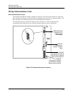
Remote controller access via dial-up modem is available via the communication setup. An external modem
is required at the controller and is connected to the standard RS232 configuration port (marked
“CONFIGURATION”). All functions of the Control Builder and User Utility programs can be performed
over this link. Remote access functions include on-line monitoring, configuration upload and download,
and firmware upgrade.
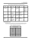
Modem requirements
Most commercially available modems can be used with the UMC800 controller. The modem must have the
following capabilities:
• RS232 interface
• Auto answer
• Can operate at 9600 baud, 8 data bits, 1 stop bit, and no parity
• Hardware handshaking can be disabled
• Software handshaking can be disabled
• Data Terminal Ready (DTR) input can be disabled
• Result codes can be suppressed
• Echo can be disabled
• Must be equipped with non-volatile memory (NVRAM) so that settings that are configured using
command strings can be retained during a power-outage
• Must be able to load the NVRAM settings automatically on power-up
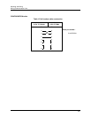
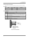
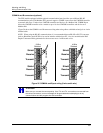
Cable requirements
You will need an interface cable to connect the modem to the DB-9 female connector (marked
“CONFIGURATION”) on the controller. If your modem has a 25-pin connector, be sure to use a DB-25 to
DB-9 modem cable.
TIP
The Null Modem cable used to directly connect a PC running Control Builder Software to the
controller may typically not be used to connect the PC to the modem or to connect the modem
to the controller.
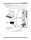
If your modem requires command string configuration, you will need an interface cable to connect the
modem to your PC. Refer to your modem and computer documentation to determine this cable’s
requirements.